Solution Builder
Solution Builder allows you to design end-to-end solutions using drag-and-drop functionality. Design an entire Network Edge solution, and then download your design with a price estimate.
Solution Builder is now generally available for all customer types except end user customers (accounts managed by Reseller accounts). Any feedback or issue can be reported by clicking Give Feedback, instead of opening the support ticket.
You can select a single virtual device, redundant device, or a cluster device and create multiple virtual connection (non-redundant) to various service providers. A price estimate for your design is generated once required fields are configured for each component.
The following components are currently supported:
| Solution / Function | Components |
|---|---|
| General |
|
| Network Edge |
|
| Equinix Fabric |
|
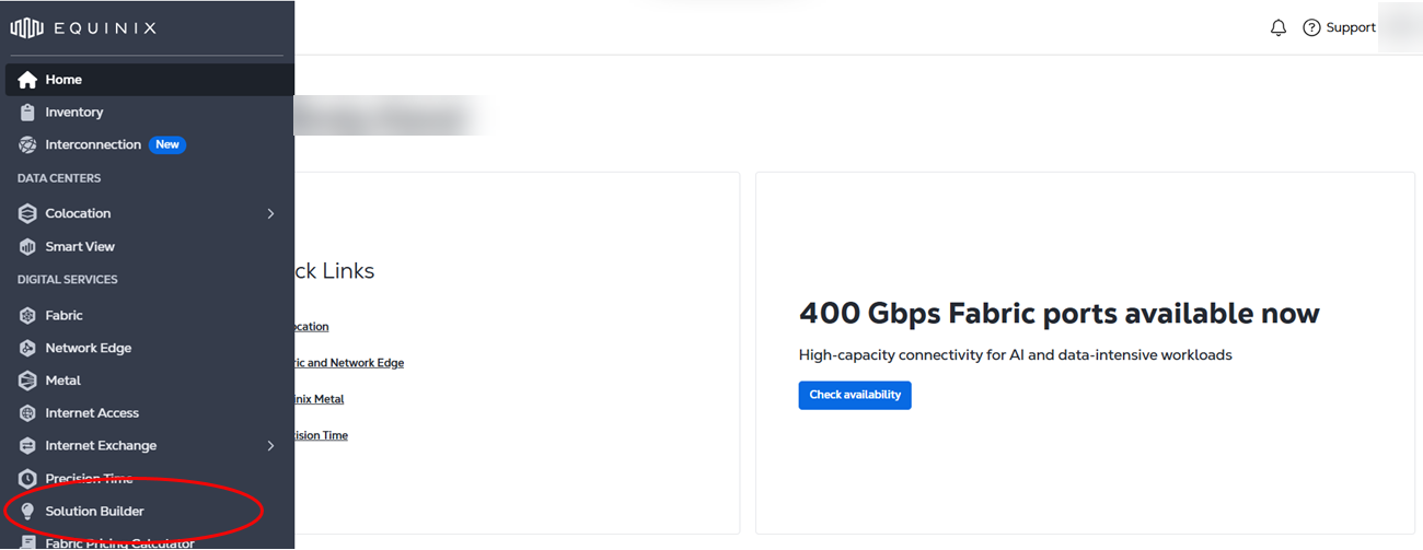
To access the Solution Builder, sign in to the Customer Portal and select Solution Builder from the main navigation.
The Solution diagram list displays all of the diagrams you have created. The Solution Diagram List displays when you have one or more design.
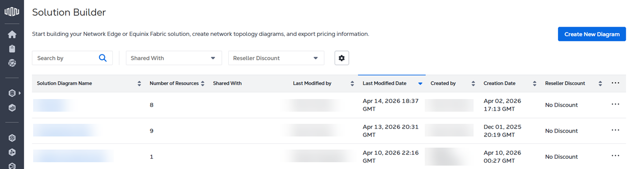
Click the ... to edit, duplicate, or delete any of the diagrams in your list.
If your organization is migrated to the Identity and Access Management experience, you can create and duplicate solution design in a project you are currently in. You cannot move or copy your design to other projects.
Use the Search field to look for specific solution design by diagram name or creator name.