Cisco Catalyst 8000V Video
This topic explains how to create and operate a Cisco Catalyst 8000V in the SD-WAN controller mode. Refer to the Cisco documentation for more information about Cisco Catalyst 8000V SD-WAN.
Prerequisites
The prerequisites for deploying Cisco Catalyst 8000V in the SD-WAN Controller mode are:
-
Cisco.com log in credentials.
-
The appropriate DNA licenses to provision and operate the Catalyst 8000V device from Cisco.com. This license is installed in vManage, not Equinix Fabric.
-
Your Cisco vManage software (controller) should be running and operational (not managed by Equinix).
Generate Bootstrap File
-
Sign into the Cisco vManage SD-WAN Controller.
-
Locate the SD-WAN edge device in the controller.
-
On the Cisco vManage menu, select Configuration > Devices.
-
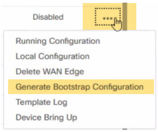
Select the logical C8000V SD-WAN you are using for a new Network Edge device, click
 and select Generate Bootstrap Configuration.
 Note: A chassis number for your C8000V is populated by syncing your Smart Account on SD-WAN Manager after your license is deposited to your Smart Account. Select any unused chassis number to generate the bootstrap file. It is important to follow Step 4 above before creating a profile.
 -
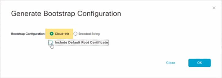
In the Generate Bootstrap Configuration box, select Cloud-Init and click OK. Selecting Include Default Root Certificate is optional.
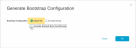
The Generate Bootstrap Configuration box displays the bootstrap configuration, including the OTP token for the license, vBond address, UUID, and organization information. -
Click Download in the Generate Bootstrap Configuration box to save a copy of the bootstrap configuration.
-
Validate your bootstrap file content to ensure that no extra information is included. The example below shows the valid format and attributes allowed in the cloud-init file to be uploaded in the C8000V device creation workflow.
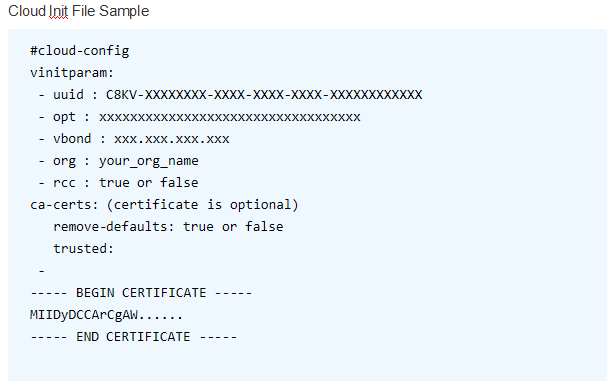
Note: This is a example of a Cloud Init file. Use the file downloaded from vManage and do not modify. For the most up-to-date documentation on the bootstrap generation, see Bootstrap Process for Cisco SD-WAN Cloud-Hosted Devices.
Create Device
- Sign in to the Equinix Customer Portal and navigate to Network Edge.
-
From the Network Edge menu, select Create Virtual Device.
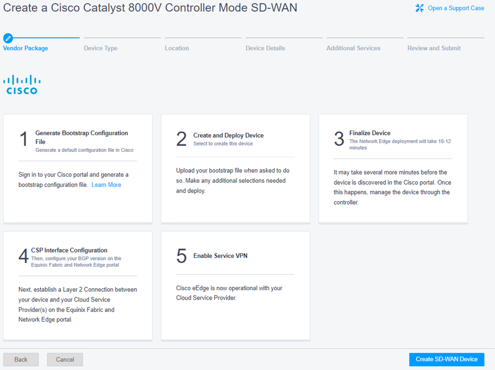
- Click Select and Continue on the Cisco 8000V (Controller Mode) card to begin device.

-
Review the steps for creating and configuring the device.

- Click Create SD-WAN Device.
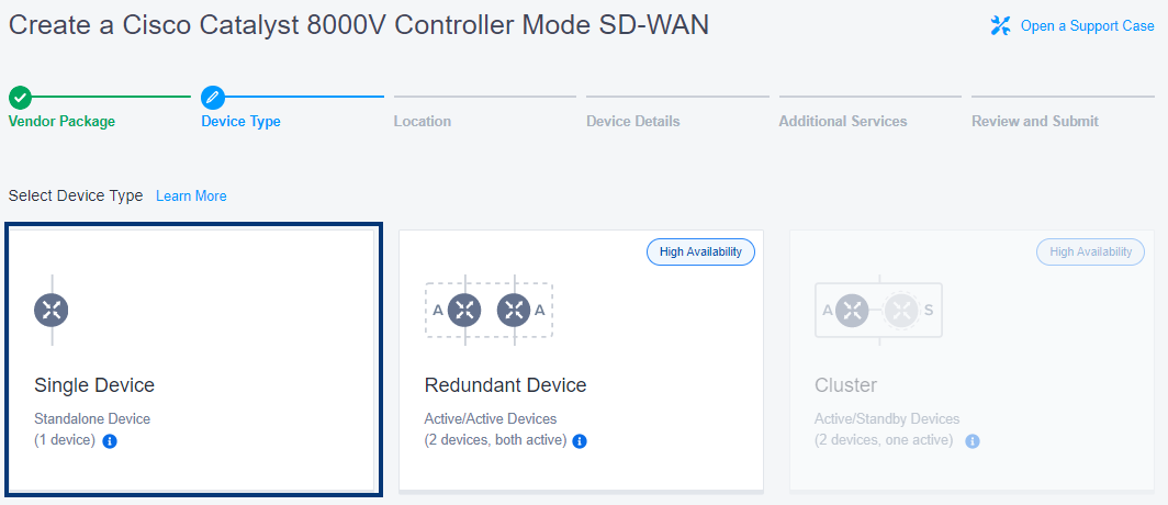
- Click Single Device. You can create redundant devices for high availability. See Achieve Resiliency Through Geo-Redundancy for more information.
- Click Begin Creating Edge Devices.
- In the Select Metro section, click a location.
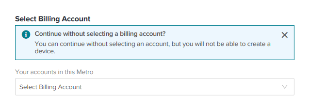
- Select a billing account.

In order to create a device in a specific metro location, you need a billing account for the metro. You can continue without selecting an account, but you won’t be able to create your device. -
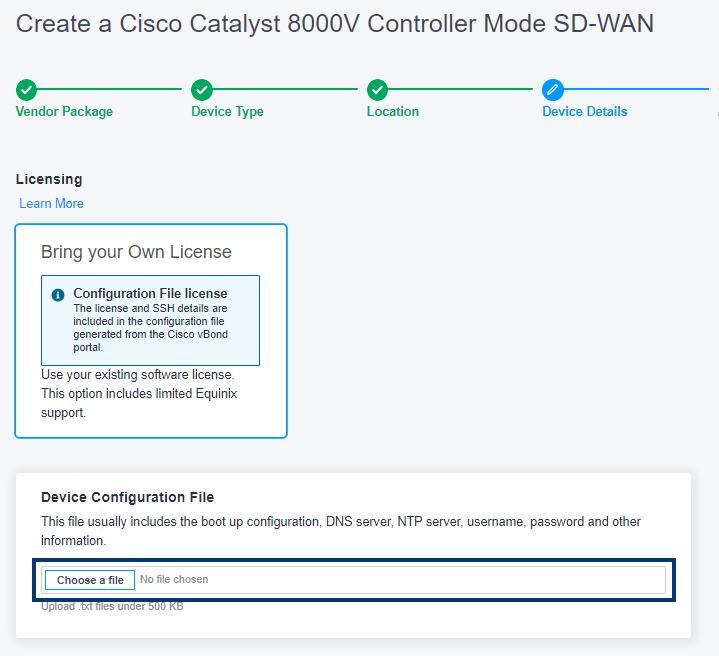
Click Next: Device Details. Bring Your Own License (BYOL) is pre-selected because it is the only option available for this VNF type.
- In the Device Configuration File section, click Choose File to upload the bootstrap files generated in the Cisco vManage Console. See the Generate Bootstrap File section.
-
Select the Device Resources.
-
Select a Software Package.
-
Select a Throughput Tier.
-
Select the Software Version.
-
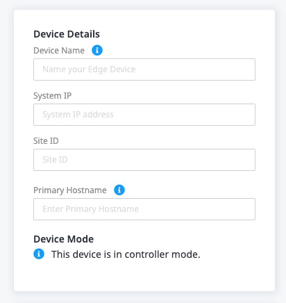
Enter the details for your device:

- Device Name – Enter a name for the device used to identify it in the portal.
- System IP – Enter the system IP address. This is a persistent IP address that identifies the Cisco device. It is similar to a router ID on a regular router, which is the address used to identify the router from which packets originated.
- Site ID – Enter the identifier of the site in the Cisco SD-WAN overlay network in which the device(s) and controllers reside.
- Primary Host Name – Enter the device host name configured for the device.
- Device Mode – Indicates that the device is in controller mode.
-
In the Interfaces section, select the number of interfaces. The 10 Interfaces option is the default, but the number can be increased to 24.

- In the Select your WAN/SSH interface section, select an option.
-
In the Device Status Notifications, enter the email addresses of anyone who should receive email notifications regarding device status.
-
(Optional) Enter the Purchase Order Number and Order Reference/Identifier.
-
Select a Term Length. The default is one month.
- Click Next: Additional Services.
- Diverse Compute from an Existing Single Device – If you already have another single device and you want this new device to exist in a different plane, click Select Diverse From and select the existing device.
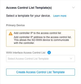
- Add Control List Templates – This access list is used to control ingress traffic toward the virtual device. The access list is applied to the adjacent gateway device where this virtual device WAN interface is connected. The access list needs to permit the vManage IP address. If you need to create an access list for this device, see Create an ACL for this Device to create an ACL that allows the vManage IP address.
- Additional Internet Bandwidth – Add between 25 and 5000 additional Mbps of internet bandwidth (for a fee).
- Click Next: Review and review your order.

Note: Click View Details on the card to see a preview of the configuration options available for this virtual device.
If a software version is being retired within the next 2 months, you will see a ![]() icon next to the version number. It is strongly recommended that you select a different version because once a version is retired, Equinix will not support it.
icon next to the version number. It is strongly recommended that you select a different version because once a version is retired, Equinix will not support it.

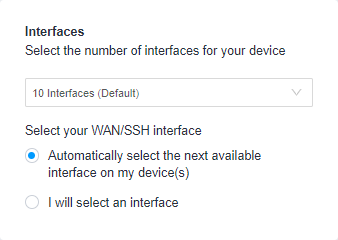
Note: The global IP address is assigned to the WAN interface. You can select which VNF virtual interface is used for WAN access. By default, the system selects the interface automatically. Select I will select an interface to manually change the WAN interface assignment.
Note: By default, the communication required for initial bootstrap (DNS, NTP, License Server communication, etc.) is allowed to properly configure the initial VNF configuration. Additional protocols such as SSH need to be intentionally permitted using a custom ACL template. See Configure Access Controls on Virtual Devices for more information.
- Click Create Virtual Device.
Create an ACL for this Device
-
Click Create Access Control List Template.

-
In the Basic Details section:
-
Template Name – Enter a name for the template.
-
Template Description – Enter a brief description of the template.
-
-
Enter the vManage IP Address in the IP Address Subnet field.
-
In the Protocol section, select IP.
-
(Optional) Provide a description of this rule.