Use Case - NTP over Anycast Using Network Edge
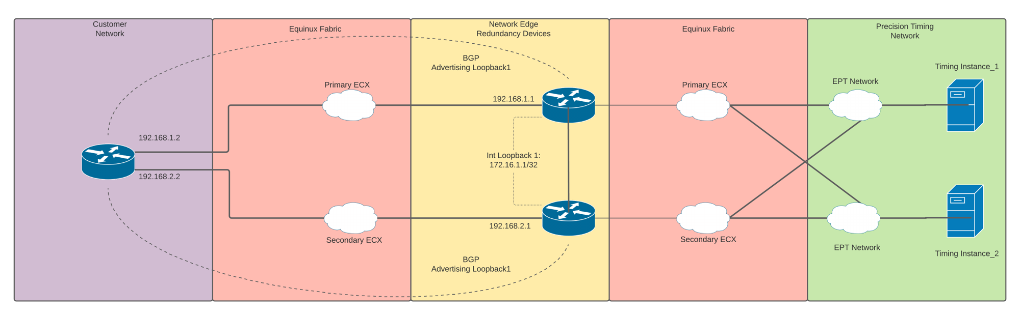
Consider this use case for handling large NTP-only service distribution across a network domain. This use case describes the steps and topology that you could use to configure Anycast for NTP using high availability and redundancy features with Network Edge and an Amazon Web Services (AWS) connection.
Network Edge-side Configuration
-
Configure routers – A pair of Network Edge routers (Cisco Catalyst 8000V) in the Equinix Fabric are configured for redundancy through the Equinix Customer portal.
- From the Equinix Customer portal, click Network Edge > Create Virtual Device > With a Redundant Device > Cisco Catalyst 8000V.
- Select Metro and add your License information.
- Select the Devices’ Resource, Software, License Throughput, Names, and number of Interfaces.
- Add user credentials and create your access list for the devices.
-
Create connections – The routers are connected to the Precision Timing network, and IP addresses are assigned to the timing instances using these values.
Primary Connection Secondary Connection Additional Buyer Options IP address 1 10.10.130.10 10.10.130.10 IP address 2 10.10.130.11 10.10.130.11 Gateway interface 10.10.130.1 10.10.130.2 Network mask 255.255.255.0 255.255.255.0 -
Configure two gateways, one per device.
-
Configure the IP addresses of your routers’ respective interfaces in the same network, and test connectivity to the IP addresses of the timing instances using
ping. -
If you plan to use an access list, you must permit the IP addresses of the timing instances and the NTP port of 123.
-
Create a
Loopback_0interface as the routers’router-idand Border Gateway Protocol (BGP) update source, using the same IP address on both Network Edge routers.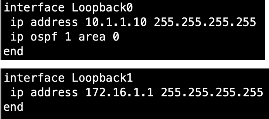
-
Configure both routers as the NTP time server, and make your
Loopback_1interface into your NTP source. Also, add your timing instance IP addresses as your NTP sources.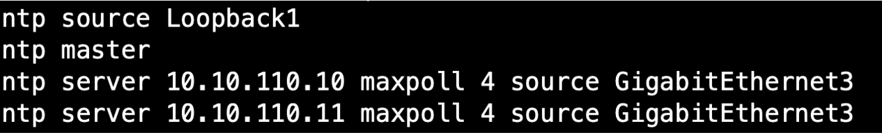
-
-
Create a connection between the two redundant devices:
- In the Network Edge device menu, go to Additional Services and create a Device Link.
- Add both Network Edge devices to the group to create a link between them.
-
Configure the IP addresses for the respective interfaces, and test connectivity.
-
Set up reachability for the BGP configuration:
-
To create reachability between the routers
Loopbacks_0, configure an Interior Gateway Protocol (IGP) on the routers. These examples shows the Open Shortest Path First (OSPF) as the IGP.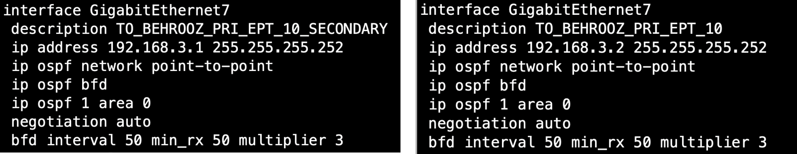
-
Configure the Bidirectional Forwarding Detection (BFD) to detect outages quickly and converge faster.
-
-
Create two separate connections to your physical routers, switch, or firewall.
-
Configure IP addresses and IGP plus BFD on your physical routers, switch, or firewall.
-
Configure the respective configuration on the Network Edge redundant routers.
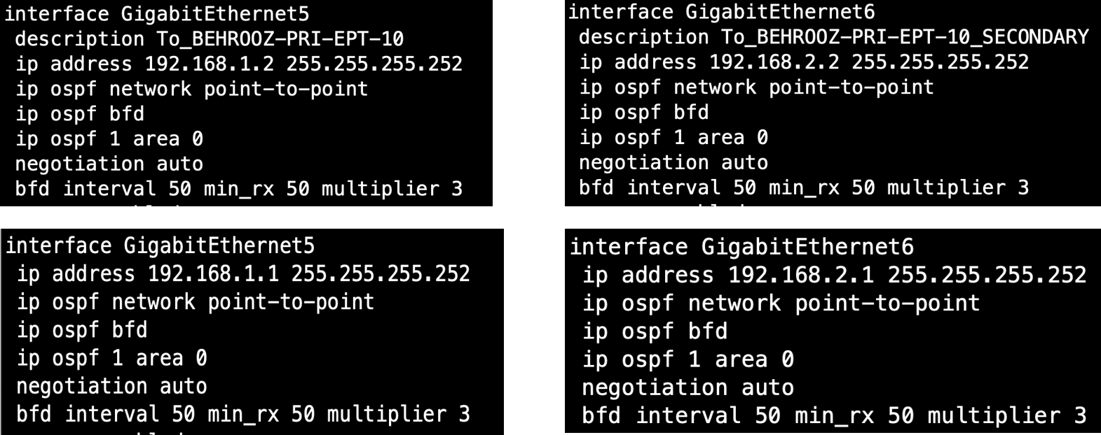
-
-
Configure BGP on the Network Edge routers and your physical routers, switch, or firewall.
-
BGP configuration on NE
Router_1– Advertiseloopback_1as your NTP source.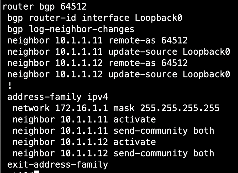
-
BGP configuration on NE
Router_2– Advertiseloopback_1as your NTP source.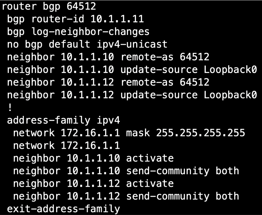
-
BGP configuration on your physical router – Advertise
loopback_1as your NTP source.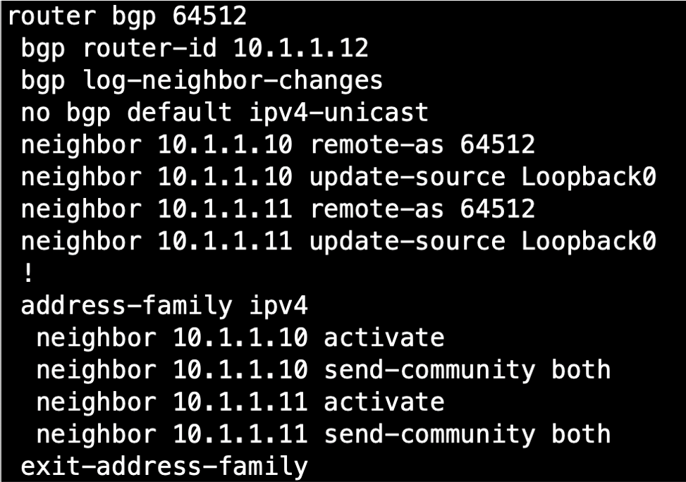
-
Check the BGP table to verify that
Loopback_1of both Network Edge routers is on your physical router.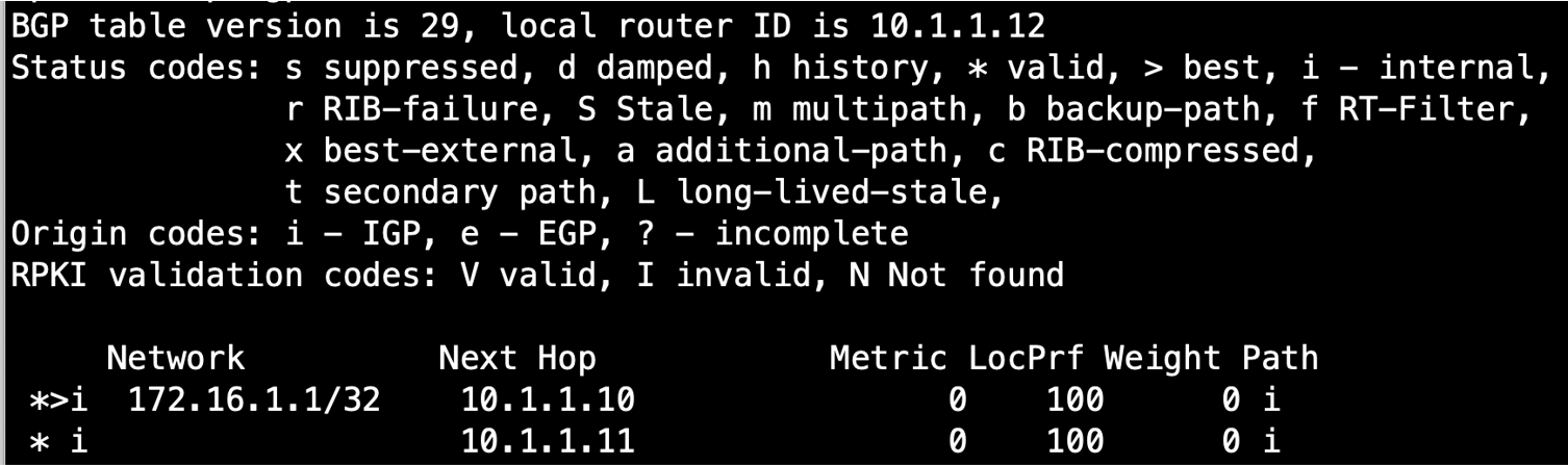
-
Configure this IP address as the NTP source on your physical routers, switch, or firewall:
ntp server 172.16.1.1 maxpoll 4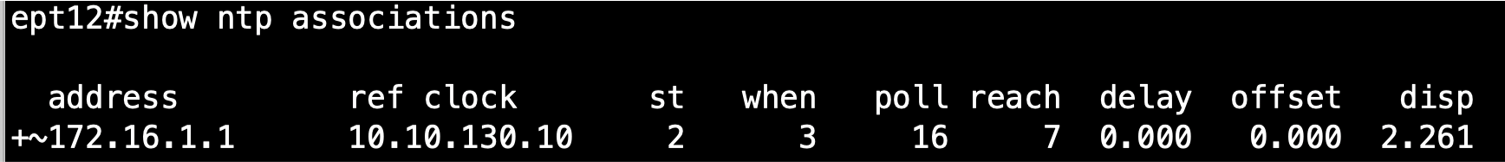
-
High Availability Configuration
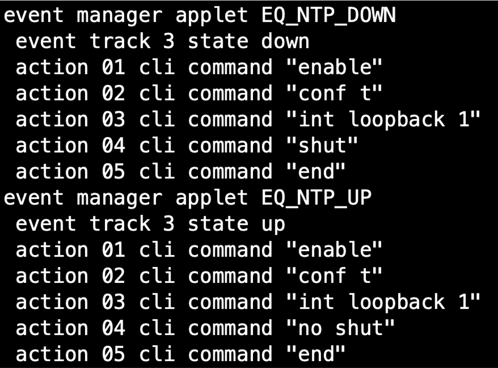
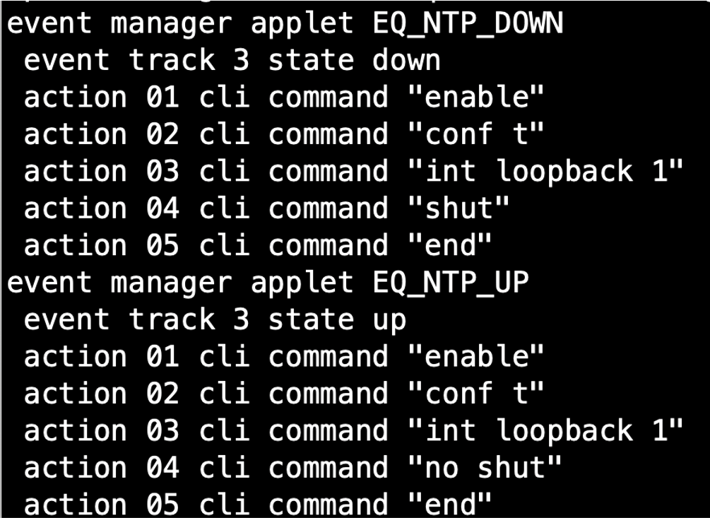
In the Anycast topology for Network Edge, the loopback interface on the Network Edge device is used as the NTP source to the client network. If connectivity from the primary Network Edge router to the precision timing source is lost, the route from the timing client to the precision timing source is no longer available.
The high availability solution described below automatically monitors and detects the connectivity to the NTP source. With this solution, the loopback interface will be shut down if connectivity is lost, then brought back up when connectivity is restored.
This solution for the Cisco Catalyst 8000V router uses a combination of IP SLA and event manager.
Create three IP SLA instances:
-
NE_1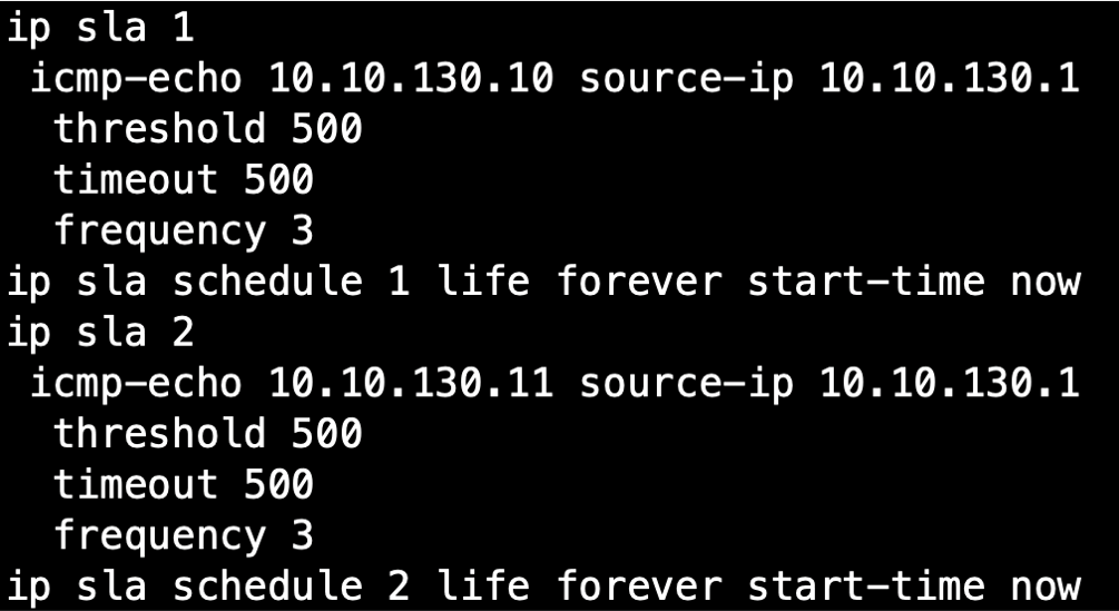
-
NE_2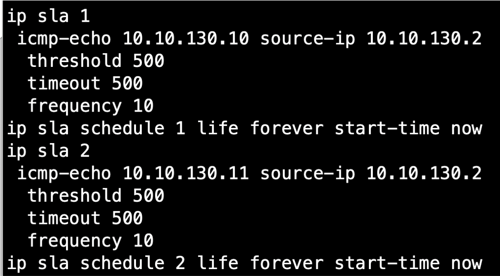
Connecting to Amazon Web Services (AWS)
To connect to AWS, the physical router from your configuration might connect to the virtual router pair, and to AWS through another interface of the same physical router. But if you use a Network Edge virtual router as your Edge router and your AWS connection, then the BGP configuration requires a small difference.
When you configure the Network Edge router through the Network Edge portal, the default configuration creates the vrfcloud address family on the router:
address-family ipv4 vrfcloud
You must create your neighbor relationships and advertisements under this address family.
-
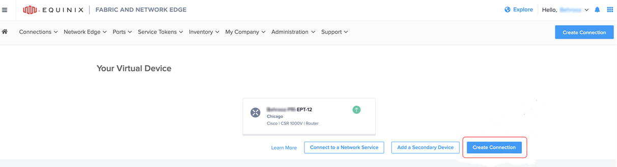
From the Network Edge device dashboard on the Equinix Customer portal, click Create Connection.
-
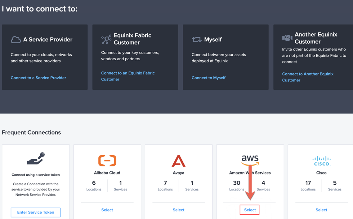
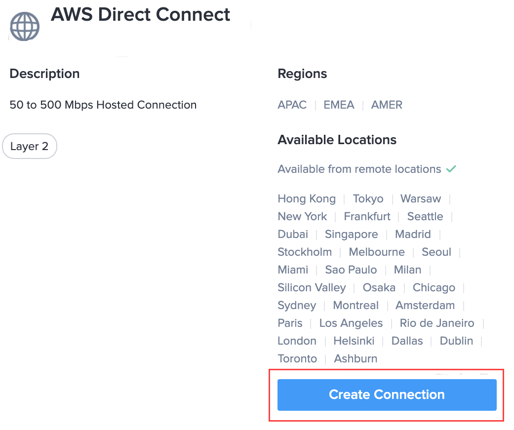
Click Connect to a Service Provider, then select AWS.
-
In AWS Direct Connect, click Create Connection.
-
Click Create a Connection to AWS Direct Connect.
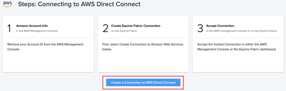
The next page displays the source and destination options for your connection.
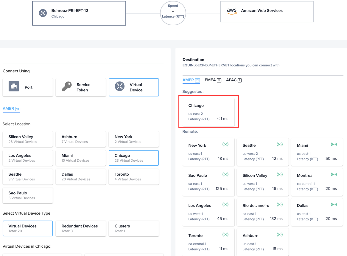
-
On the left side of the page, the location and device type of your Network Edge virtual device is selected. On the right side, select the Destination for your AWS region, then click Next.
-
In the next page, enter the following information:
- Virtual Connection Name
- AWS Account ID
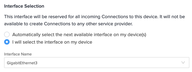
- Interface Selection – The interface from which you want to create the AWS connection
-
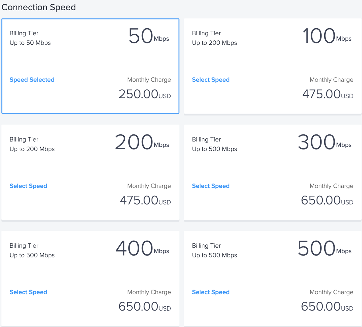
Select the connection speed.
-
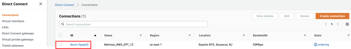
Log into your AWS account, and navigate to Direct Connect Dashboard > Connections. Click the connection order and accept it.
-
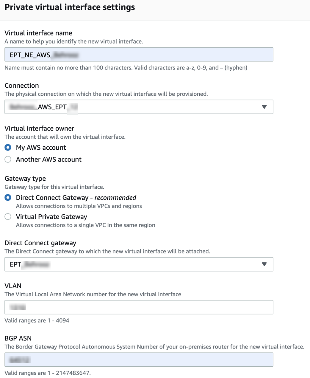
In your AWS account, navigate to Direct Connect Dashboard > Create a Virtual Interface. Bind it to the connection that you just created on Equinix Fabric and accepted in your AWS account.
-
Enter the required information.
-
Bind the virtual interface to the connection and the Direct Connect Gateway for your Virtual Private Cloud (VPC).
-
-
In the Additional Settings, add the peering interfaces and your AWS VGW BGP AS number.
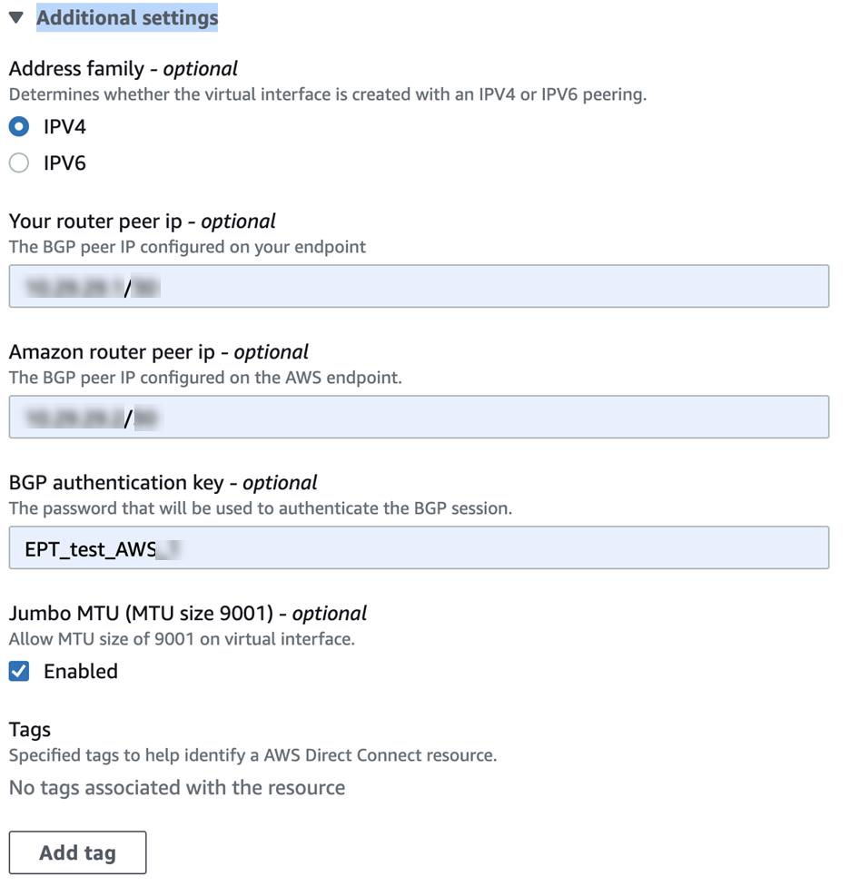
After a few minutes, your BGP status displays as up.

Network Edge-related BGP Configuration
This configuration is set up under the address-family ipv4 vrfcloud:
1  | address-family ipv4 vrf cloud
2  |   network 10.12.12.0 mask 255.255.255.0
3  |   neighbor 10.0.0.10 remote-as 64512
4  |   neighbor 10.0.0.10 activate
5  |   neighbor 10.0.0.11 remote-as 64512
6  |   neighbor 10.0.0.11 activate
7  |   neighbor 10.29.29.2 remote-as 64521
8  |   neighbor 10.29.29.2 password 7 <08047C7A...>
9  |   neighbor 10.29.29.2 activate
10 | exit-address-family
Advertise your VPC CIDR as a local route in your AWS VPC routing table, and you'll receive the NTP Anycast IP address 172.16.1.1.