Equinix Metal was sunset on June 30, 2026. The user documentation will be removed on September 30, 2026.
Hybrid Unbonded Mode
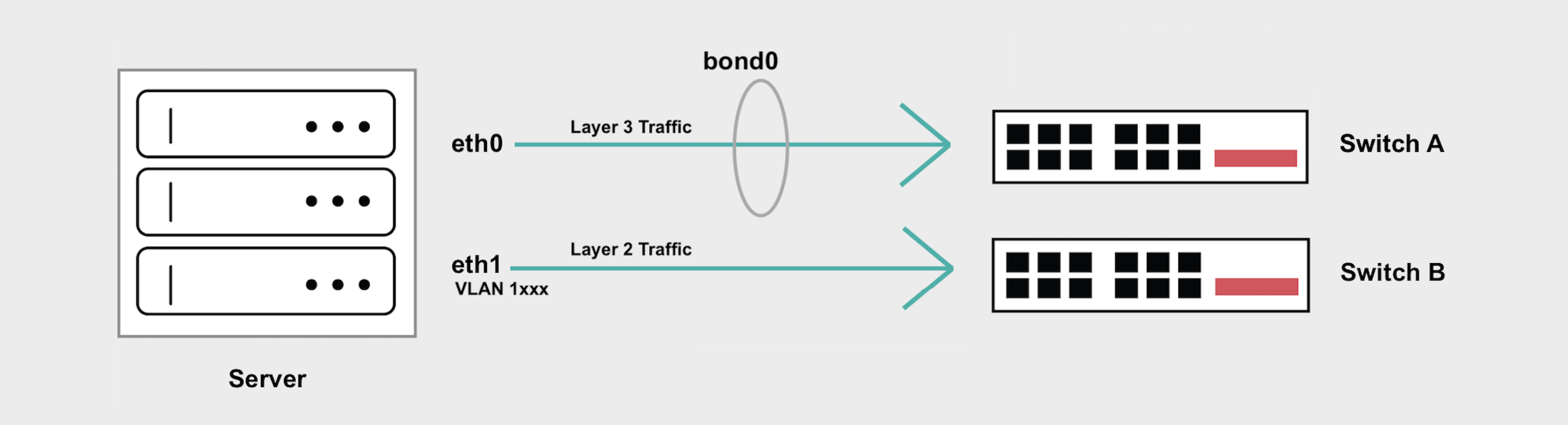
In Hybrid Unbonded mode one network interface is removed from the Layer 3 bond and placed in Layer 2 mode. VLANs can then be assigned to this interface for Layer 2 connectivity while preserving the Layer 3 connectivity, so the server can still be accessed at its public IP address.
Although this is desirable in some situations, it introduces a single point of failure either on the upstream switch or the network interface. An outage, maintenance event, or reboot on either one of the switches will cause network interruptions.
If you have high-availability concerns, the Hybrid Bonded mode supports both Layer 2 and Layer 3 while maintaining the highly available “bonded” networking interface that spans 2 diverse upstream switches.
General Overview
- Hybrid Unbonded Mode breaks
eth1out of the bond, and Layer 3 traffic will no longer flow overeth1. - You can then add VLANs to
eth1for your Layer 2 traffic. If you are only adding one VLAN toeth1, traffic must not be tagged. - If you are adding more than one VLAN to
eth1, you will need to create subinterfaces to handle tagged traffic for each VLAN and/or you have to set a Native VLAN to handle untagged traffic. bond0will continue to handle your Layer 3 traffic, and Internet access is preserved through your Equinix Metal assigned public IP address.- If you add VLANs to
bond0, you will need to create subinterfaces to handled tagged traffic for each VLAN.bond0does not support untagged Layer 2 traffic or setting a Native VLAN.
Converting to Hybrid Unbonded Mode
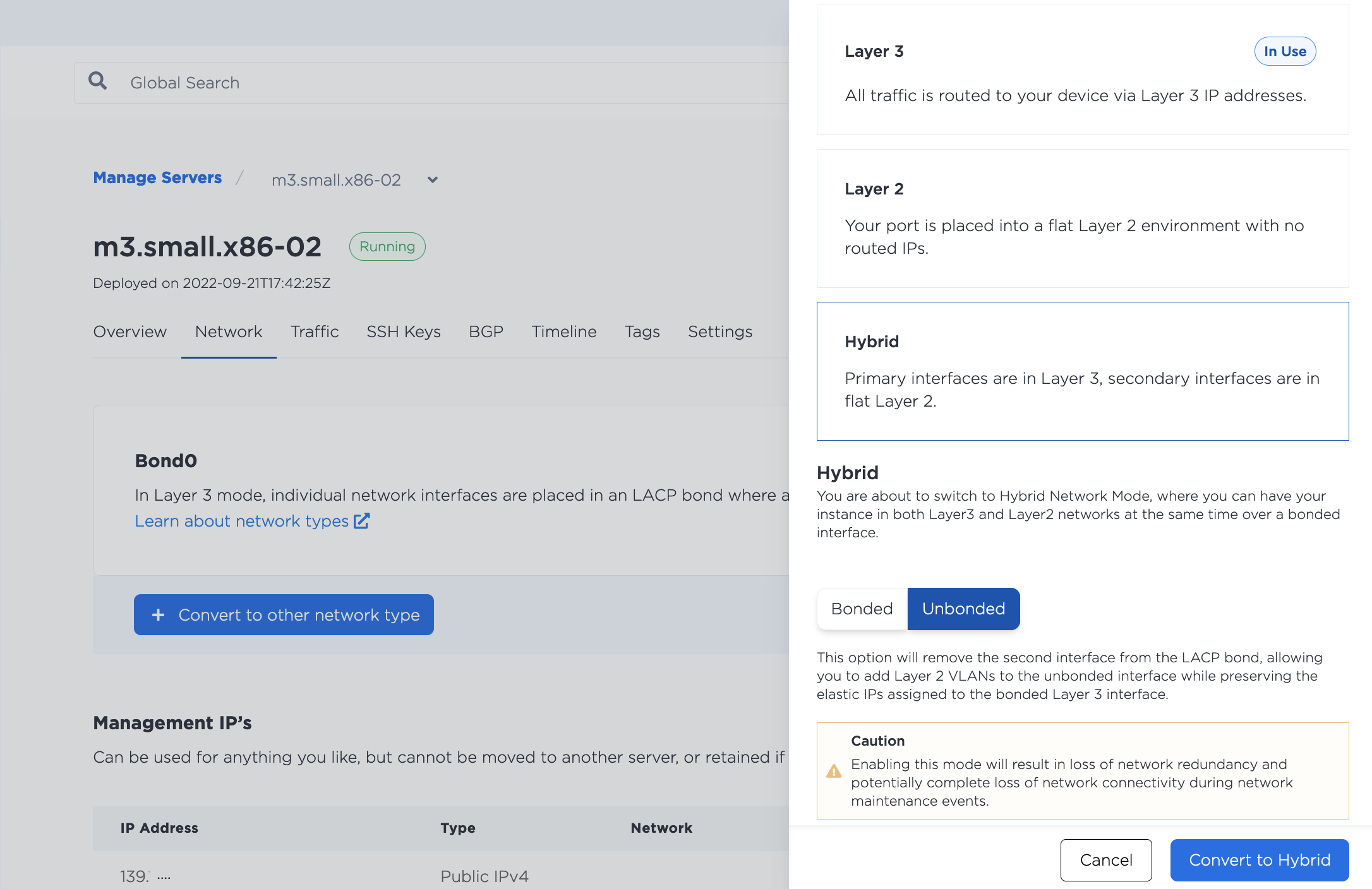
Hybrid Unbonded mode removes the eth1 interface from the LACP bond, allowing you to add Layer 2 VLANs to eth1 while preserving the elastic IPs assigned to the bonded Layer 3 interface.
- Console
- CLI
- API
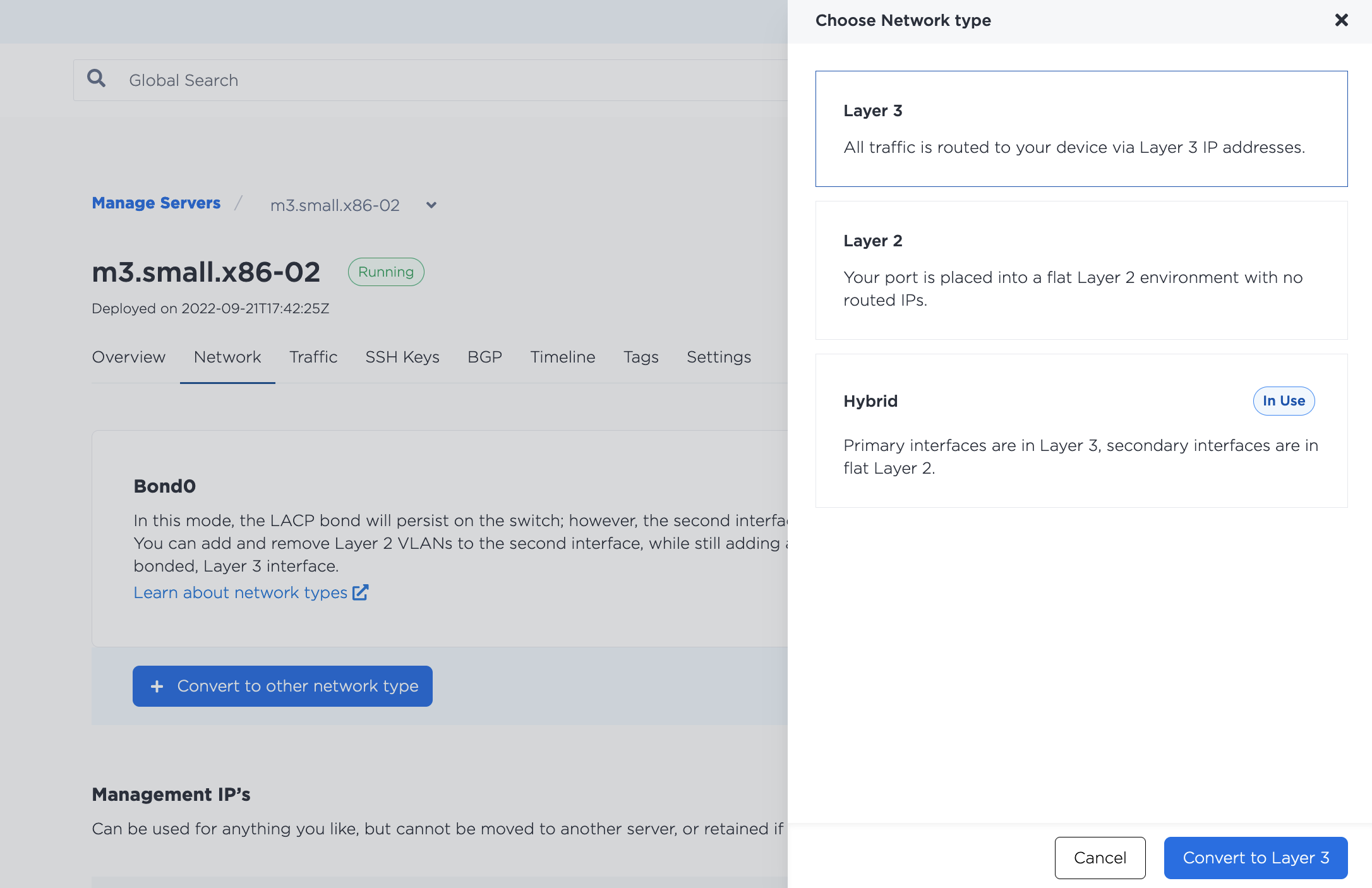
In order to use Hybrid Unbonded mode, you must first change your networking configuration to Hybrid mode. In the console, navigate to the server's Network tab, click Convert To Other Network Type, select Hybrid, and choose Unbonded. Click Convert to Hybrid to make the changes.
Then, from the server's Network page, click Add New VLAN. Choose eth1 as the interface and select the Virtual Network ID (VNID, or VLAN ID) you wish to use.
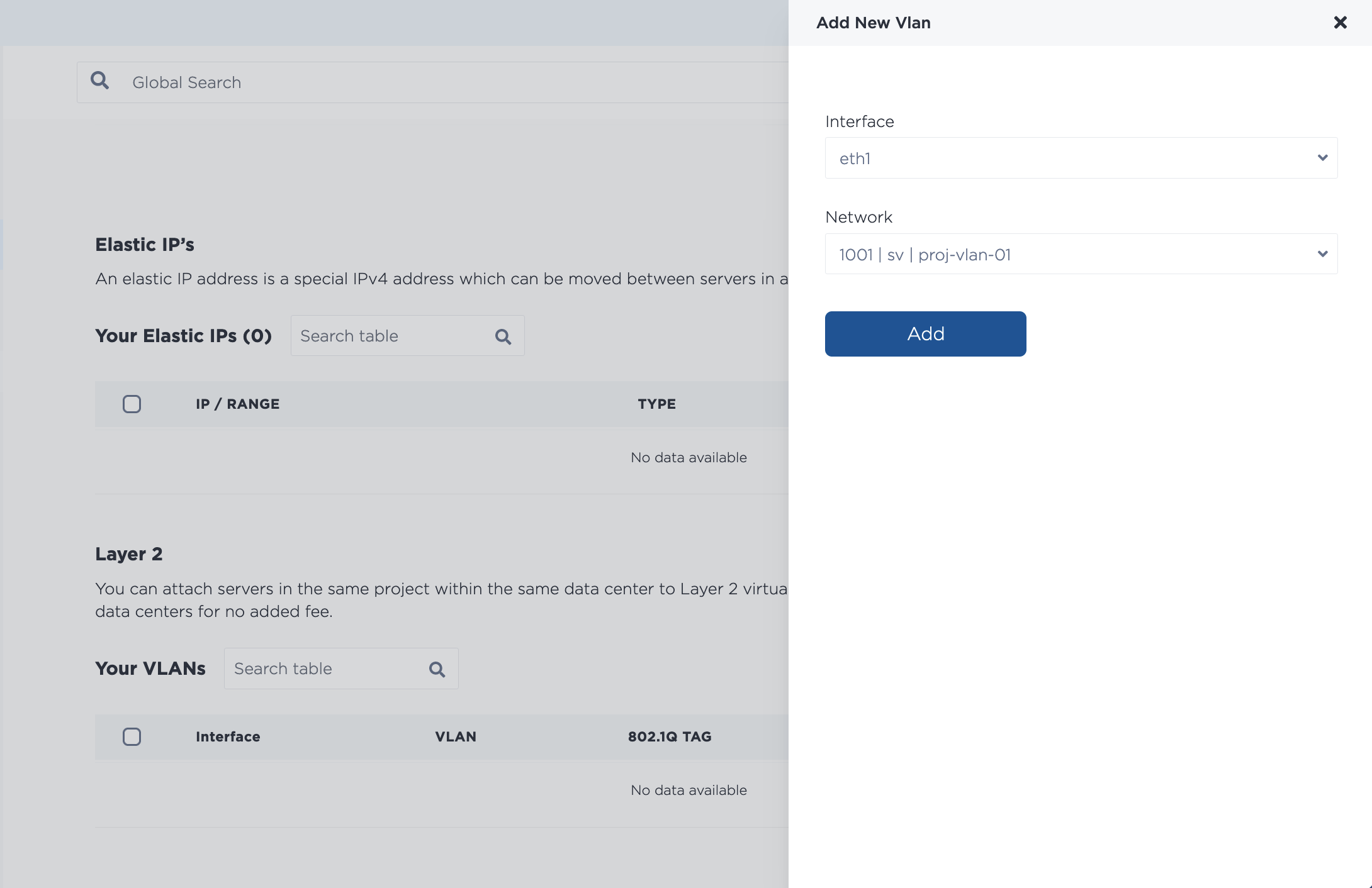
To assign multiple VLANs at once, keep adding VLANs from the drop-down. Note that if you assign multiple VLANs at once, they are added through an asynchronous batch process, which begins immediately, but may take some time to complete.
First, remove the eth1 port from the bonded network interface with the metal port convert command. The use the UUID of the eth1 port as the --port-id and set its --bonded state to false.
metal port convert --port-id <eth1_id> --bonded=false
Then, assign a VLAN to eth1 with the metal port vlan command. Specify the UUID of eth1 for the --port-id and the VLAN that you are assigning to --assign.
metal port vlan --port-id <eth1_id> --assign <VLAN_id>
The VLAN_id can be either the VLAN's UUID or the VLAN ID number that is in the console.
First, you will need to remove eth1 from the bond. Send a POST request to the /ports/{id}/disbond endpoint.
You have to specify the port ID of eth1 in the path, and it needs to be the UUID for that port as returned by the /devices/{id} endpoint.
Set the bulk_disable field to false in the body of the request.
curl -X POST \
-H "Content-Type: application/json" \
-H "X-Auth-Token: <API_TOKEN>" \
"https://api.equinix.com/metal/v1/ports/{id}/disbond" \
-d '{
    "bulk_disable": false
}'
Then, you need to assign your VLAN to eth1. Send a POST request to the /ports/{id}/assign endpoint.
curl -X POST \
-H "Content-Type: application/json" \
-H "X-Auth-Token: <API_TOKEN>" \
"https://api.equinix.com/metal/v1/ports/{id}/assign" \
-d '{
    "vnid": "<vlan_ID>"
}'
The 'vnid' is the ID of the VLAN that is sent in the body of the request. The ID an be either the VLAN's UUID as returned by the /projects/{id}/virtual-networks endpoint, or the VLAN ID that is in the console.
It is also possible to assign VLANs to a port in bulk, as part of an asynchronous batch process. Send a POST request to the /ports/{id}/vlan-assignments/batches endpoint an array of VLAN assignments in the body of the request.
curl -X POST \
-H "Content-Type: application/json" \
-H "X-Auth-Token: <API_TOKEN> " \
"https://api.equinix.com/metal/v1/ports/{id}/vlan-assignments/batches" \
-d '{
    "vlan_assignments": [
        {
            "vlan": "string",
            "state": "assigned"
        },
        {
            "vlan": "string",
            "state": "assigned"
        },
    ]
}'
Configuring Your Servers
Once you have converted the server to Hybrid Unbonded mode and assigned the VLAN to eth1, you will need to configure the networking on the server's operating system and assign it an IP address on the VLAN.
Note: Using the subnet starting with 10.x.x.x for your VLAN traffic is not recommended as we use this for the server's private networking and collisions could occur if you use the same subnet.
There are two example configurations, the first example is a configuration for assigning a single VLAN to eth1, the second example is for assigning multiple VLANs to eth1 and/or for assigning VLANs to bond0.
For a Single VLAN on eth1
If you have only one VLAN, do not tag the traffic, and assign the VLAN IP Address directly to the interface.
The following examples use a VLAN with VLAN ID 1036 and subnet 198.51.100.0/24.
- iproute2
- nmcli
iproute2 is a utility for managing networking configurations in the Linux kernel. It is included in most Linux operating system distributions.
In our OS images interfaces are not aliased to eth1 and eth0. In this example eth1 in the console corresponds to enp1s0f1 in the operating system.
-
Bring down the
enp1s0f1interface.ip link set down enp1s0f1 -
Make sure
enp1s0f1has been removed frombond0.ip -d link show enp1s0f1If it hasn't been removed, remove it.
ip link set enp1s0f1 nomaster -
Configure
enp1s0f1with an IP address for the VLAN. The example uses IP address198.51.100.4/24.ip addr add 198.51.100.4/24 dev enp1s0f1 -
Bring up the interface, and check that it is back up.
ip link set dev enp1s0f1 upip -d link show enp1s0f1
-
Optional: To make the networking configuration permanent and survive server reboots, edit
enp1s0f1in the/etc/network/interfacesfile.auto enp1s0f1iface enp1s0f1 inet manualaddress 192.168.1.2netmask 255.255.255.248pre-up sleep 4And also remember to remove
enp1s0f1frombond0(truncated example).auto bond0iface bond0 inet static...bond-slaves enp1s0f0dns-nameservers 147.75.207.207 147.75.207.208...
nmcli is the CLI tool for Network Manager, a utility for managing network configurations in Rocky Linux, RHEL, and CentOS Streams.
In our operating system images interfaces are not aliased to eth1 and eth0. In this example eth1 in the console corresponds to enp1s0f1 in the operating system.
-
Remove
enp1s0f1frombond0.nmcli connection delete "System enp1s0f1" -
Create a new connection for the
enp1s0f1interface of typeethernet. The example uses the name "vlan-enp1s0f1" as a convenience.nmcli connection add con-name vlan-enp1s0f1 type ethernet ifname enp1s0f1 -
Configure the connection with an IP address for the VLAN. The example uses IP address
198.51.100.5/24.nmcli connection modify vlan-enp1s0f1 ipv4.addresses 198.51.100.5/24nmcli connection modify vlan-enp1s0f1 ipv4.method manual -
Bring up the connection.
nmcli connection up vlan-enp1s0f1
You need to run through the same steps on all the servers that you want to attach to the VLAN, assigning a different IP address to each.
For Multiple VLANs on eth1 or VLANs on bond0
If you are using multiple VLANs on eth1, or if you are adding VLANs to bond0, IP packets will have the to be tagged, and you will need to setup subinterfaces that will receive packets destined for each VLAN. If you need support for untagged packets, set the VLAN that handles the untagged packets as the Native VLAN.
The following examples use eth1 and:
- A VLAN with VLAN ID
1036and subnet198.51.100.0/24. - A VLAN with VLAN ID
2025and subnet203.0.113.0/24.
- iproute2
- nmcli
iproute2 is a utility for managing networking configurations in the Linux kernel. It is included in most Linux operating system distributions.
In our OS images interfaces are not aliased to eth1 and eth0. In this example eth1 in the console corresponds to enp1s0f1 in the operating system.
-
Install and configure the prerequisites for VLANs, if you haven't already.
apt-get install vlanmodprobe 8021qecho "8021q" >> /etc/modules -
Make sure
enp1s0f1has been removed frombond0.ip -d link show enp1s0f1If it hasn't been removed, remove it.
ip link set dev enp1s0f1 nomaster -
Add new subinterfaces on
enp1s0f1to handle tagged traffic, one for each VLAN. The example uses VLAN IDs1036and2025.ip link add link enp1s0f1 name enp1s0f1.1036 type vlan id 1036ip link add link enp1s0f1 name enp1s0f1.2025 type vlan id 2025 -
Assign IP addresses to the subinterfaces. The example uses
198.51.100.2/24and -
Bring up the interfaces, and check that they came up.
ip link set dev enp1s0f1.1036 upip -d link show enp1s0f1.2025ip link set dev enp1s0f1.1036 upip -d link show enp1s0f1.2025
-
Optional: To make the networking configuration permanent and survive server reboots, add the new subinterfaces to the
/etc/network/interfacesfile.auto enp1s0f1.1036iface enp1s0f1.1036 inet staticaddress 198.51.100.2netmask 255.255.255.0vlan-raw-device enp1s0f1auto enp1s0f1.2025iface enp1s0f1.2025 inet staticaddressnetmask 255.255.255.0vlan-raw-device enp1s0f1And also remember to remove
enp1s0f1frombond0(truncated example).auto bond0iface bond0 inet static...bond-slaves enp1s0f0dns-nameservers 147.75.207.207 147.75.207.208...
nmcli is the CLI tool for Network Manager, a utility for managing network configurations in Rocky Linux, RHEL, and CentOS Streams.
In our operating system images, the interfaces are not aliased to eth1 and eth0. In this example eth1 in the console corresponds to enp1s0f1 in the operating system.
-
Enable VLAN and tagged interface support.
echo 8021q > /etc/modules-load.d/8021q.conf -
Remove
enp1s0f1from the bond.nmcli connection delete "System enp1s0f1" -
Create a new connection that adds a subinterface on
enp1s0f1to handle tagged traffic. The example uses VLAN IDs1036and2025.nmcli connection add type vlan con-name enp1s0f1.1036 ifname enp1s0f1.1036 vlan.parent enp1s0f1 vlan.id 1036nmcli connection add type vlan con-name enp1s0f1.2025 ifname enp1s0f1.2025 vlan.parent enp1s0f1 vlan.id 2025 -
Assign IP addresses from your VLAN subnets to the connections. The examples uses IP addresses
198.51.100.3and203.0.113.3.nmcli connection modify enp1s0f1.1036 ipv4.addresses '198.51.100.3/24' ipv4.method manualnmcli connection modify enp1s0f1.1036 ipv4.addresses '203.0.113.3/24' ipv4.method manual -
Bring up both connections
nmcli con up enp1s0f1.1036nmcli con up enp1s0f1.2025
You will need to run through the same steps on all the servers that you want to attach to the VLANs, assigning different IP addresses to each.
Testing the VLAN Connection
You should now be able to communicate between the servers on your VLAN Layer 2 network.
[root@nmcli-testing ~]# ping 198.51.100.2
>
PING 198.51.100.2 (198.51.100.2) 56(84) bytes of data.
64 bytes from 198.51.100.2: icmp_seq=1 ttl=64 time=0.703 ms
64 bytes from 198.51.100.2: icmp_seq=2 ttl=64 time=0.444 ms
64 bytes from 198.51.100.2: icmp_seq=3 ttl=64 time=0.451 ms
64 bytes from 198.51.100.2: icmp_seq=4 ttl=64 time=0.412 ms
^C
--- 198.51.100.2 ping statistics ---
4 packets transmitted, 4 received, 0% packet loss, time 3113ms
rtt min/avg/max/mdev = 0.412/0.502/0.703/0.116 ms
Converting Back to Layer 3
If you want to go back to the default Layer 3 Bonded mode, you must first remove any assigned VLANs, and then add eth1 back to the bonded interface.
- Console
- CLI
- API
To unassign a VLAN in the console, navigate to the server's Network tab. In the Layer 2 section, select the VLAN you are unassigning from the port. Click Remove.
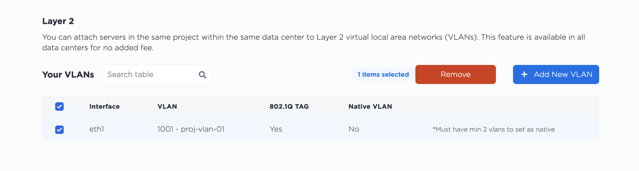
Note that unassigning the VLAN does NOT delete it from your project. The VLAN will continue to exist after unassigning it from the port.
Then, to convert back to Layer 3, click Convert To Other Network Type, select Layer 3. Click Convert to Layer 3 to start the process.
Unassign VLANs from the eth1 interface with the metal port vlan command. Specify the UUID of eth1 for the --port-id and the VLAN that you are unassigning to --unassign.
metal port vlan --port-id <eth1_id> --unassign <vlan>
Then, return eth1 to the bond with the metal port convert command.
metal port convert -i <eth1_id> --bonded=true
To unassign a VLAN from a port, sent a POST request to the /ports/{id}/unassign endpoint.
You have to specify the port ID of eth1 in the path, and ID of the VLAN in the body of the request. It can be either the VLAN's UUID or the VLAN ID that is in the console.
curl -X POST \
-H "Content-Type: application/json" \
-H "X-Auth-Token: <API_TOKEN>" \
"https://api.equinix.com/metal/v1/ports/{id}/unassign" \
-d '{
        "vnid": "1173"
    }'
You can also unassign multiple VLANs from a port in bulk, as part of an asynchronous batch process. Send a POST request to the /ports/{id}/vlan-assignments/batches endpoint an array of VLAN assignments in the body of the request, and their state set to "unassigned".
curl -X POST \
-H "Content-Type: application/json" \
-H "X-Auth-Token: API_TOKEN" \
"https://api.equinix.com/metal/v1/ports/{id}/vlan-assignments/batches" \
-d '{
    "vlan_assignments": [
        {
            "vlan": "string",
            "state": "unassigned"
        },
        {
            "vlan": "string",
            "state": "unassigned"
        }
    ]
}'
Then, you return the port to the Layer 3 bond. Send a POST request to the /ports/{id}/bond endpoint.
curl -X POST \
-H "Content-Type: application/json"\
-H "X-Auth-Token: <API_TOKEN>" \
"https://api.equinix.com/metal/v1/ports/{id}/bond" \
-d '{
    "bulk_enable": false
}'