Equinix Metal was sunset on June 30, 2026. The user documentation will be removed on September 30, 2026.
Hybrid Bonded Mode
Equinix Metal™ allows users to change the networking mode of servers from the default Layer 3 Bonded mode to a Hybrid Bonded Layer 3 and Layer 2 mode.
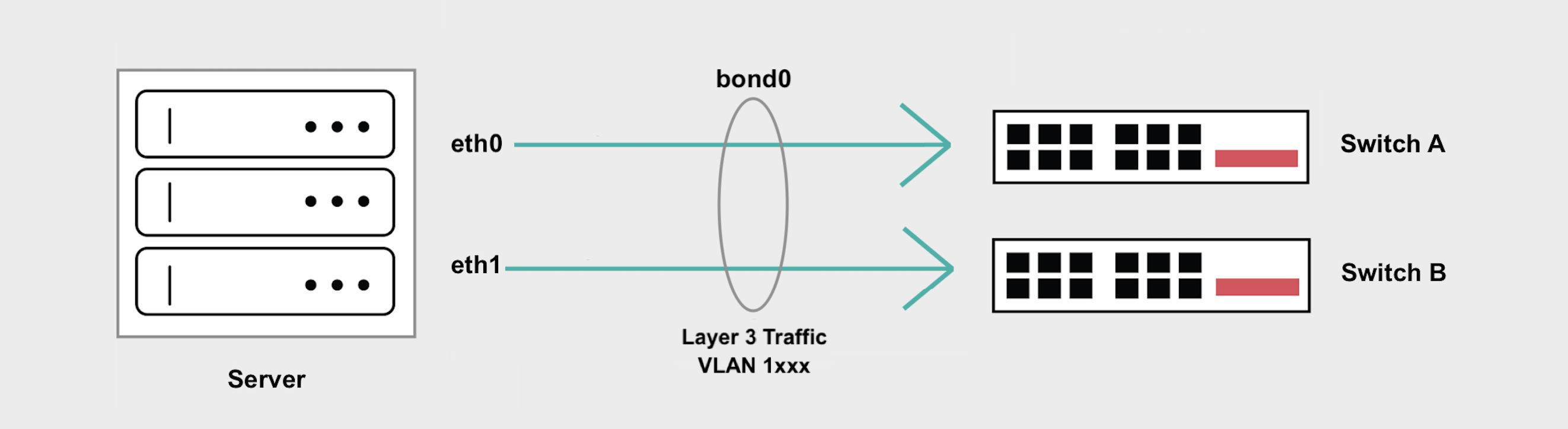
Hybrid Bonded mode enables a highly available “bonded” setup of 2 networking interfaces that supports both Layer 2 and Layer 3 modes at the same time. This keeps the functionality of supporting both Layer 2 and Layer 3, but does so while maintaining a highly available bonded networking interface that spans 2 diverse upstream switches.
This is a way to implement common hybrid cloud networking models such as running firewalls, custom gateways, ingress controllers and other types of proxies that face the Internet on one side and private Layer 2 infrastructure on the other side.
General Overview
- In Hybrid Bonded Mode all Layer 3 and Layer 2 traffic is handled on
bond0. - Your server's Internet access is preserved through your Equinix Metal assigned public IP address.
- Layer 3 traffic is untagged.
- All Layer 2 traffic has to be tagged and handled by subinterfaces on
bond0, one for every VLAN. - Hybrid Bonded mode does not support untagged Layer 2 traffic or setting a Native VLAN.
Enabling Hybrid Bonded Mode
Enabling Hybrid Bonded mode can be done by assigning a VLAN to the bonded interface on your server.
- Console
- CLI
- API
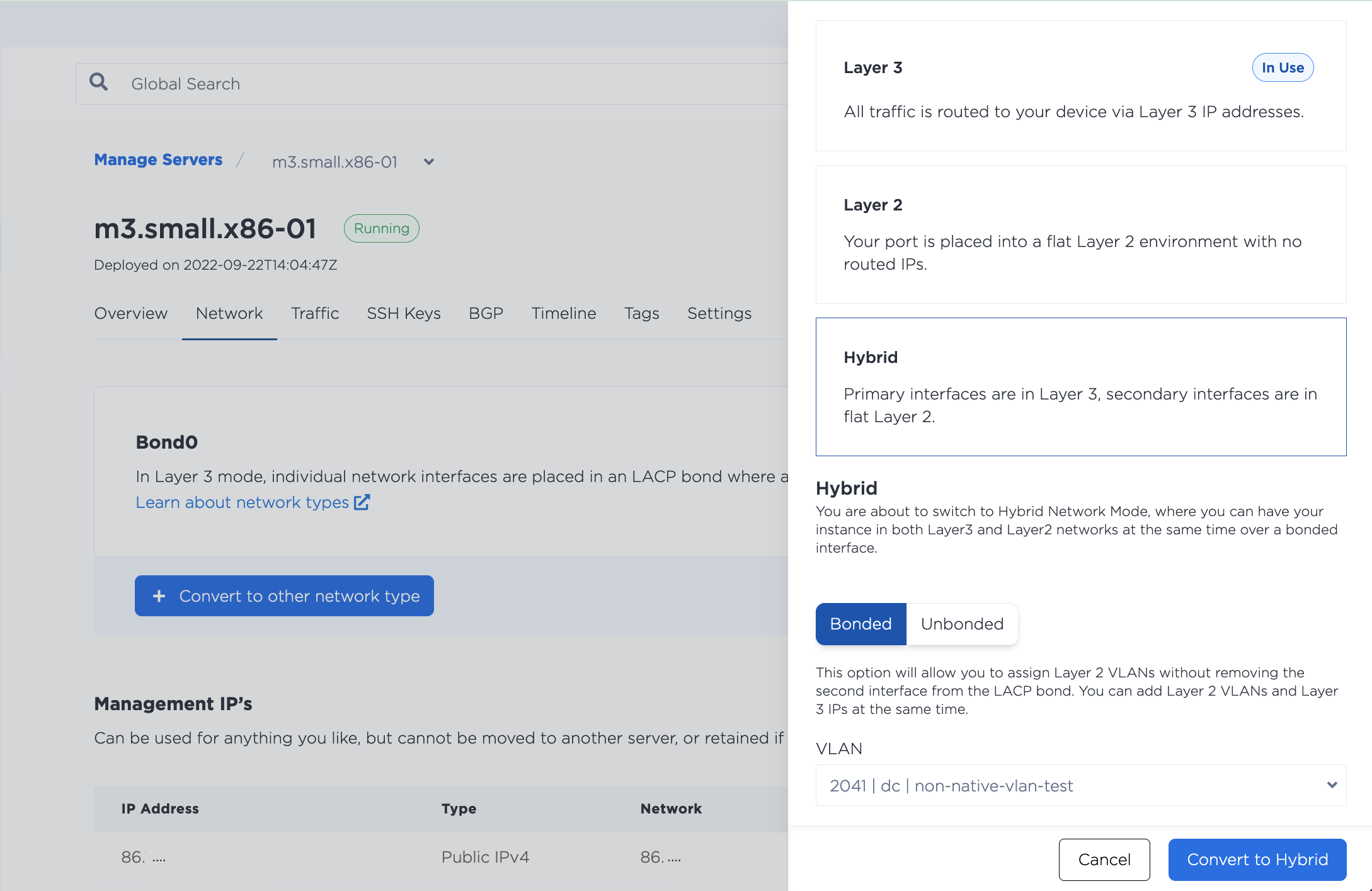
In the Equinix Metal console, navigate to the server's Network tab, click Convert To Other Network Type, select Hybrid, and choose Bonded.
Then, select the VLAN from the drop-down, which will allow you to assign a VLAN to the bond0 interface. Click Convert to Hybrid to start the changes.
In the CLI, assign a VLAN to the bonded interface, bond0, with the metal port vlan command.
metal ports vlan --port-id <bond0_id> --assign <VLAN_id>
Specify the UUID of bond0 for the --port-id and the VLAN that you are assigning to --assign.
In the API, you assign a VLAN to a port by sending a POST to the /ports/{id}/assign endpoint. Specify the UUID of a port in the path. For Hybrid Bonded mode, it needs to be the UUID for bond0 as returned by the /devices/{id} endpoint.
curl -X POST \
-H "Content-Type: application/json" \
-H "X-Auth-Token: <API_TOKEN> " \
"https://api.equinix.com/metal/v1/ports/{id}/assign" \
-d '{
    "vnid": "<vlan_ID>"
    }'
Body Parameters:
"vnid"(required) - The ID of the VLAN. The ID can be either the VLAN's UUID as returned by the/projects/{id}/virtual-networksendpoint, or the VLAN ID that is in the console.
Configuring Your Servers
Once you have assigned the VLAN to bond0, you will need to configure the networking on the server's operating system. Because traffic from both Layer 3 and the VLAN are going through bond0, you will need to create a subinterface to handle the tagged traffic over the VLAN. Hybrid Bonded mode does not support untagged VLAN traffic or setting a Native VLAN.
The following examples use a VLAN with VLAN ID 1036 and subnet 198.51.100.0/24.
Note: Using the subnet starting with 10.x.x.x for your VLAN traffic is not recommended as we use this for the server's private networking and collisions could occur if you use the same subnet.
- iproute2
- nmcli
iproute2 is a utility for managing networking configurations in the Linux kernel. It is included in most Linux operating system distributions.
-
Install and configure the prerequisites for VLANs and tagged interfaces.
apt-get install vlanmodprobe 8021qecho "8021q" >> /etc/modules -
Add a new subinterface on
bond0to handle tagged traffic. The example uses VLAN ID1036.ip link add link bond0 name bond0.1036 type vlan id 1036 -
Assign an IP address from your VLANs subnet to the subinterface. The examples uses IP address
198.51.100.2.ip addr add 198.51.100.2/24 dev bond0.1036 -
Bring up the interface, and check that it came up.
ip link set dev bond0.1036 upip -d link show bond0.1036
-
Optional: To make the networking configuration permanent and survive server reboots, add the new subinterface to the
/etc/network/interfacesfile.auto bond0.1036iface bond0.1036 inet staticpre-up sleep 5address 198.51.100.2/24netmask 255.255.255.0vlan-raw-device bond0Note: The line
pre-up sleep 5helps to prevent conflicts onbond0when the server boots.
nmcli is the CLI tool for Network Manager, a utility for managing network configurations in Rocky Linux, RHEL, and CentOS Streams.
-
Enable VLAN and tagged interface support.
echo 8021q > /etc/modules-load.d/8021q.conf -
Add a new subinterface on
bond0to handle tagged traffic. The example uses VLAN ID1036.nmcli connection add type vlan con-name bond0.1036 ifname bond0.1036 vlan.parent bond0 vlan.id 1036 -
Assign an IP address from your VLANs subnet to the subinterface. The examples uses IP address
198.51.100.3.nmcli connection modify bond0.1036 ipv4.addresses '198.51.100.3/24'nmcli connection modify bond0.1036 ipv4.method manualnmcli con up bond0.1036
You need to run through the same steps on all the servers that you want to attach to the VLAN, assigning a different IP address from the subnet to each.
Adding Multiple VLANs
Adding multiple VLANs to the bond is supported, you just have to make sure there is a subinterface that will receive packets destined for each VLAN.
- Console
- CLI
- API
To assign another VLAN, or to assign multiple VLANs at once, navigate to the server's Network page. In the Layer 2 section, click Add New VLAN, to assign the VLAN to the bond0 port.
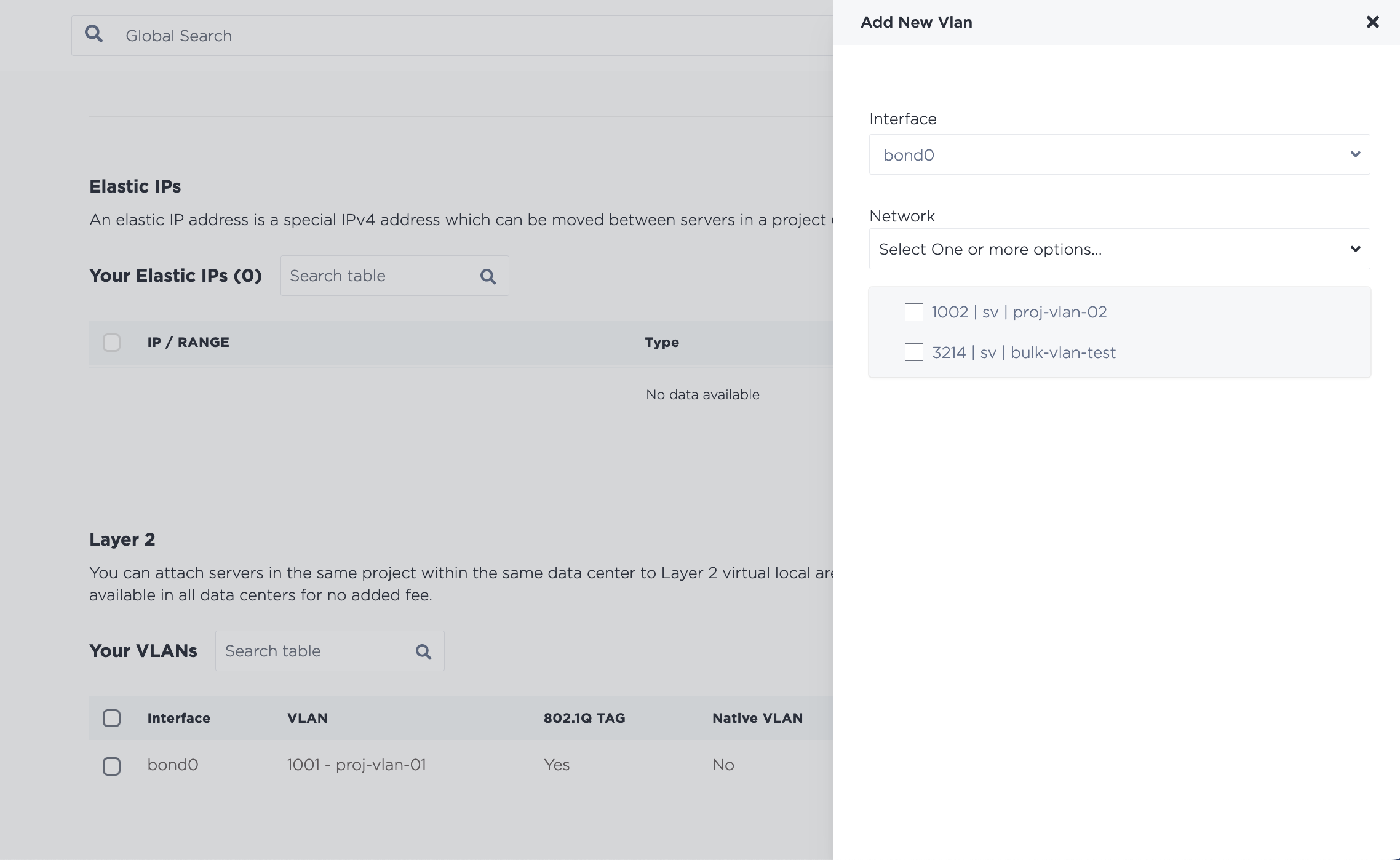
Click Add to start the changes. Note that if you assign multiple VLANs at once, they are added through an asynchronous batch process, which begins immediately, but may take some time to complete.
To assign another or multiple more VLANs, use the metal port vlan command, and specify each VLAN you are assigning to bond0.
metal port vlan --port-id <bond0_id> --assign <vlan> --assign <vlan>
The procedure for assigning one more VLAN to the port in the API is the same assigning the first VLAN. Send a POST request to the /ports/{id}/assign endpoint, where the UUID of bond0 is the port ID in the path and the VLAN you want to assign is specified in the body of the request.
curl -X POST \
-H "Content-Type: application/json" \
-H "X-Auth-Token: <API_TOKEN> " \
"https://api.equinix.com/metal/v1/ports/{id}/assign" \
-d '{
    "vnid": "<vlan_id>"
    }'
It is also possible to assign VLANs to a port in bulk, as part of an asynchronous batch process. Send a POST request to the /ports/{id}/vlan-assignments/batches endpoint an array of VLAN assignments in the body of the request.
curl -X POST \
-H "Content-Type: application/json" \
-H "X-Auth-Token: <API_TOKEN> " \
"https://api.equinix.com/metal/v1/ports/{id}/vlan-assignments/batches" \
-d '{
    "vlan_assignments": [
        {
            "vlan": "string",
            "state": "assigned"
        },
        {
            "vlan": "string",
            "state": "assigned"
        },
    ]
}'
The VLAN can be identified by either the VLAN's UUID or the VLAN ID that is in the console. Since you are assigning the VLAN to the ports, the "state" field should be "assigned".
Once the VLANs are assigned to bond0, repeat the process for configuring your servers to create the additional tagged subinterfaces for each VLAN.
Testing the VLAN Connection
You should now be able to communicate between the servers on your VLAN Layer 2 network.
root@dev-02:~# ping 198.51.100.2
>
PING 198.51.100.2 (198.51.100.2) 56(84) bytes of data.
64 bytes from 198.51.100.2: icmp_seq=1 ttl=64 time=0.898 ms
64 bytes from 198.51.100.2: icmp_seq=2 ttl=64 time=0.659 ms
64 bytes from 198.51.100.2: icmp_seq=3 ttl=64 time=0.649 ms
64 bytes from 198.51.100.2: icmp_seq=4 ttl=64 time=0.421 ms
^C
--- 198.51.100.2 ping statistics ---
4 packets transmitted, 4 received, 0% packet loss, time 3037ms
Converting Back to Layer 3
To go back to the default Layer 3 networking configuration, remove any and all VLANs from bond0.
- Console
- CLI
- API
To unassign a VLAN from a port, navigate to the server's Network tab. In the Layer 2 section, select the VLAN or VLANs you are detaching from the server and click Remove.
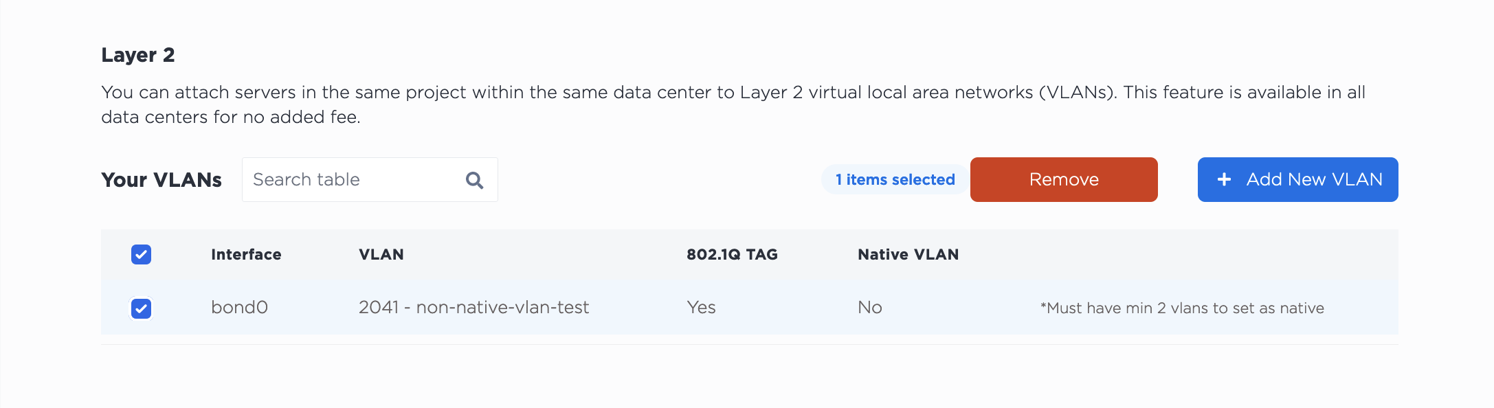
Note that detaching the VLAN from this server does NOT delete it from your project. The VLAN will continue to exist after detaching it from the server.
In the CLI, unassign a VLAN from bond0, with the metal port vlan command.
metal ports vlan --port-id <bond0_id> --unassign <vlan>
Specify the UUID of bond0 for the --port-id and the VLAN that you are unassigning to --unassign.
If you are removing multiple VLANs, specify each VLAN you are removing.
metal port vlan --port-id <bond0_id> --unassign <vlan> --unassign <vlan>
In the API, you unassign a VLAN from a port by sending a POST to the /ports/{id}/unassign endpoint, where the UUID of bond0 is the port ID in the path and the VLAN you want to unassign is specified in the body of the request.
curl -X POST \
-H "Content-Type: application/json" \
-H "X-Auth-Token: <API_TOKEN> " \
"https://api.equinix.com/metal/v1/ports/{id}/unassign" \
-d '{
    "vnid": "<vlan_id>"
    }'
You can also unassign multiple VLANs from a port in bulk, as part of an asynchronous batch process. Send a POST request to the /ports/{id}/vlan-assignments/batches endpoint an array of VLAN assignments in the body of the request, and their state set to "unassigned".
curl -X POST \
-H "Content-Type: application/json" \
-H "X-Auth-Token: API_TOKEN" \
"https://api.equinix.com/metal/v1/ports/{id}/vlan-assignments/batches" \
-d '{
    "vlan_assignments": [
        {
            "vlan": "string",
            "state": "unassigned"
        },
        {
            "vlan": "string",
            "state": "unassigned"
        }
    ]
}'
Once all the VLANs are removed from the port, bond0 will be back on Layer 3 mode. From there you can use any other of the existing network modes.