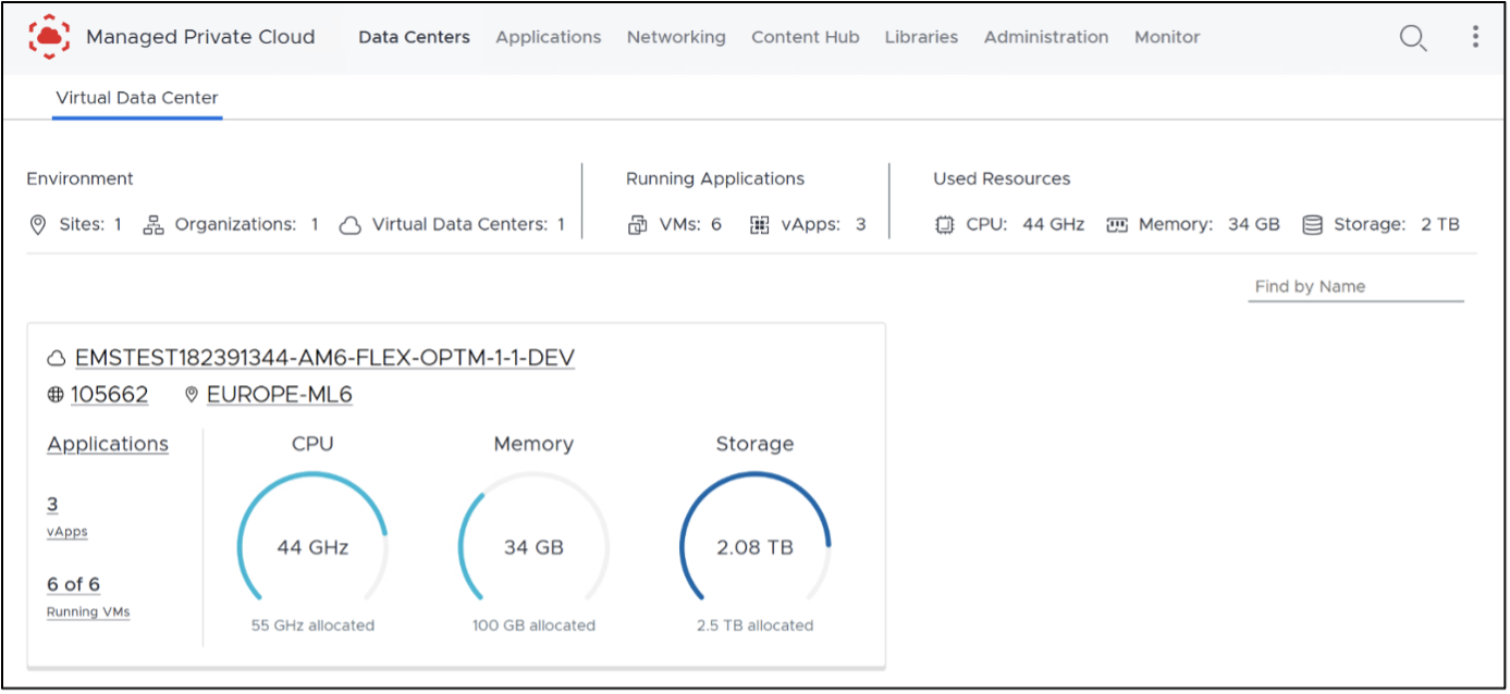
Managed Private Cloud Flex
MPC Flex is the shared-infrastructure service variant of Managed Private Cloud (MPC) for customers that require flexibility and scalability. It uses a shared tenancy model that enables dynamic allocation of resources based on workload requirements.
MPC Flex provides a multi-tenant compute environment deployed as an Organizational Virtual Data Center (OVDC) with logical separation between tenants, supporting scalability and administrative control.
An OVDC provides compute resources (vCPU and vRAM) and storage resources for creating virtual machines. Multiple OVDCs can be combined in different variants and sizes to support different purposes. Security policies can be configured on virtual networks and interconnections. Compute, storage, and networking resources are managed from the MPC Operational Console.
MPC Compute
MPC Compute consists of Processing Capacity in vCPU available for the OVDC.
vCPU
Processing capacity is available in vCPU. There are two vCPU variants that can be selected per OVDC:
- Optimized - Balances CPU capacity across the OVDC for an optimized performance.
- Full - Provides 100% of the CPU capacity.
Recommended vCPU utilization:
| VCPU Variant | Use (Examples) |
|---|---|
| Optimized (Default) | • Generic production servers • OTA servers |
| Full | • Terminal servers • High-load application servers • Latency-sensitive application servers |
The maximum number of vCPU for a VM is 32 vCPU.
MPC Memory
MPC Memory consists of memory in GB vRAM available for the OVDC.
vRAM
Memory in the OVDC is provided as vRAM, available at 100% of its capacity and measured in gigabytes (GB). The sales volume for MPC Flex uses a default compute‑to‑memory ratio:
- MPC Flex Optimized - 1 vCPU : 4 GB vRAM
- MPC Flex Full - 1 vCPU : 16 GB vRAM
The maximum capacity of vRAM for a VM is 256 GB.
Compute Purchase Units
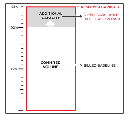
Purchase MPC Compute in Units (PUs) of vCPU and GB vRAM, using Baseline and Overage calculation types.
- Baseline represents the committed volume of PUs with a fixed monthly recurring charge.
- Overage covers the additional consumed volume above the Baseline, metered and calculated monthly.
| Purchase Unit & UOM | CPU Variant | Calculation Type | Description |
|---|---|---|---|
| vCPU | Optimized Full | Baseline | Committed volume of PUs |
| vCPU | Optimized Full | Overage | Additional consumption above Baseline |
| Purchase Unit | UOM | Calculation Type | Description |
|---|---|---|---|
| GB vRAM | GB vRAM | Baseline | Committed volume of PUs |
| GB vRAM | GB vRAM | Overage | Additional consumption above Baseline |
The default ratio of combined compute purchase units is one vCPU plus four GB vRAM (1vCPU+4GBvRAM).
Consuming Overage
OVDCs are provisioned with additional capacity for flexible consumption. This additional capacity is calculated as a percentage of the Baseline volume, with a maximum of 25%.
MPC Storage
MPC Storage provides two performance tiers represented as storage policies. Storage capacity is associated with a specific OVDC.
A virtual disk for a virtual machine (VM) can be created within the customer‑assigned storage capacity and placed on the storage policy (performance tier) that matches the VM’s workload. An OVDC can support multiple storage policies, allowing VMs within the same OVDC to use different policies.
| Storage Policy | Use |
|---|---|
| High Performance | Database workloads, logs, RDS/SBC, VDI, and other low‑latency–sensitive workloads |
| Performance (Default) | Generic VMs, applications and web services, high‑performance file services, and object storage |
MPC Storage Features
The following features apply when using storage policies in the MPC environment:
- Storage capacity is allocated per policy per OVDC
- MPC Storage includes encryption at rest
MPC Storage Per VM
The recommended virtual disk size per VM is between 40 GB and 8 TB.
MPC Storage Purchase Units
MPC Storage is measured in purchase units (PUs) of 1 TB per storage policy, with Baseline and Overage calculation types.
- Baseline represents the committed volume of storage with a fixed monthly recurring charge.
- Overage represents additional consumed volume beyond the Baseline, metered and calculated monthly.
| Purchase Unit | Tier | Calculation Type | UOM | Description |
|---|---|---|---|---|
| MPC Storage | High Performance | Baseline | 1 TB | Baseline charge for the committed storage quantity, measured in whole TBs. |
| MPC Storage | Performance | Overage | 1 TB | Charge for storage usage that exceeds the Baseline quantity, measured in TBs with up to 3 decimal places. |
Note: Storage capacity is calculated based on the following assumptions: 1TB = 1000GB. Storage capacity is not transferable to other OVDCs.
Consuming Overage
MPC Storage is provisioned per storage policy with additional capacity available for flexible consumption. Additional capacity is calculated as a percentage of the Baseline volume, with a maximum of 25% or 10 TB.
MPC Storage Consumption
The storage consumption per policy is measured as allocated capacity for:
- VM disks
- VM swap files
- Snapshots
- Files in a library (vApp templates and ISOs)
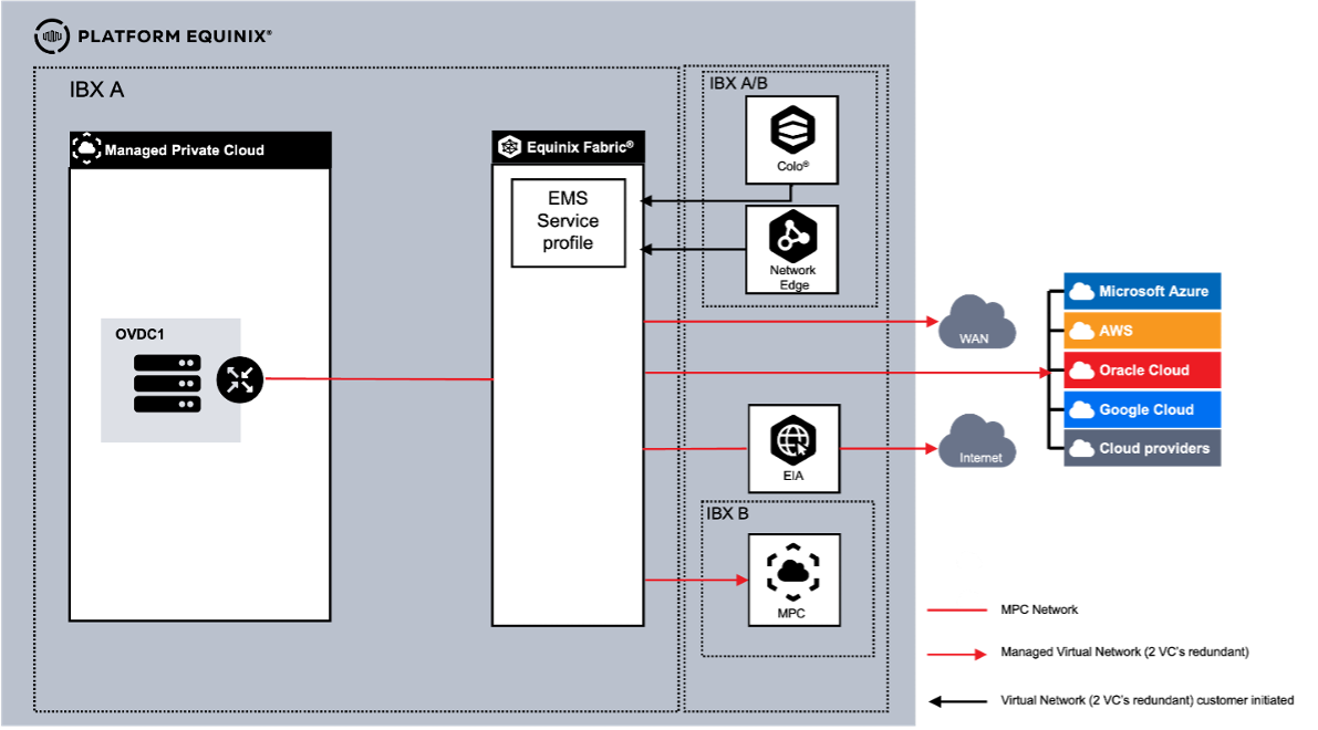
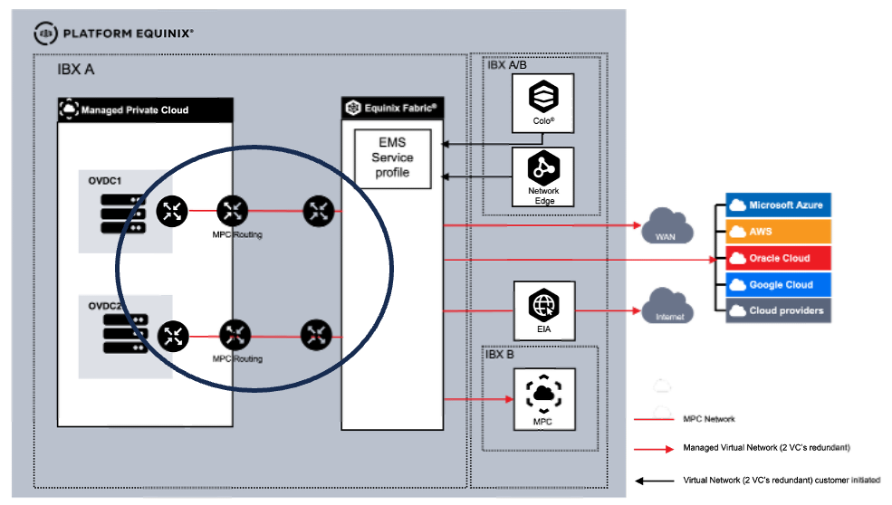
MPC Connectivity
To make MPC an integral part of customers' (multi) cloud architecture, MPC can be connected to the following external environments:
- Equinix Colocation
- Equinix Network Edge
- WAN Providers
- Cloud Service Providers (CSP)
- MPC environments in another metro
- Equinix Internet Access (EIA) via Equinix Fabric
Connectivity is supported through Equinix Fabric using Virtual Circuits. Other connectivity options are not supported.
Connectivity Type
Network requirements determine how customer networks connect to an MPC Organizational Virtual Data Center (OVDC). The following connectivity types are available:
| Connectivity Type | Routing Management |
|---|---|
| Routed | Routing in MPC provided by Equinix |
| Routed Joined | Option for routing only with multiple OVDCs |
| Customer Routed | Routing provided by the customer as a virtual appliance in the OVDC |
| Managed Private Firewall | Routing provided through the Service Managed Private Firewall service |
Multiple OVDCs
Each OVDC has its unique connectivity type. When multiple OVDCs are used, supported combinations of connectivity types are available.
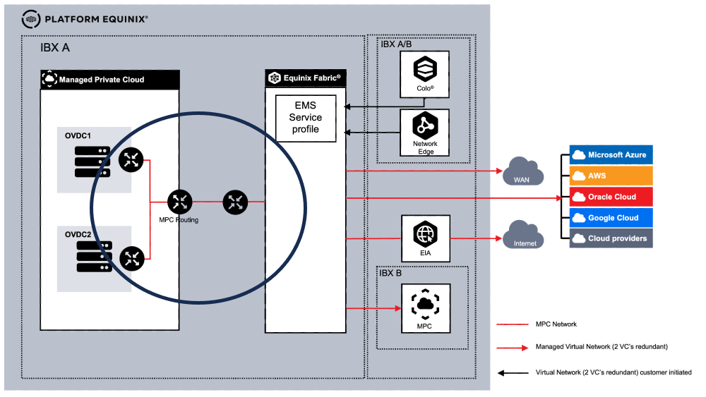
Connectivity Routed
This connectivity type provides layer-3 connectivity to the MPC OVDC for connectivity. This option provides the customer with a ready for use and built-in routing engine. Configurable via the operational console. Each MPC internal (routed) network created is automatically part of the customer routing domain.
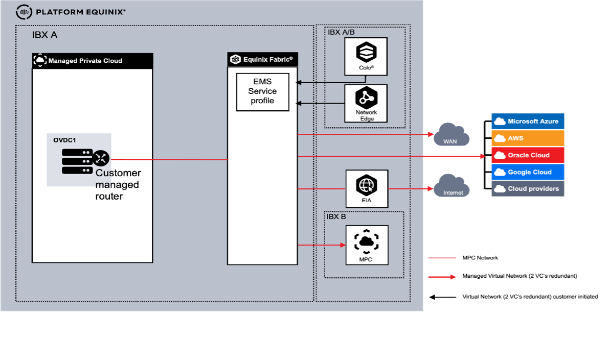
Connectivity Customer Routed
This option provides the customer with a self-provided, installed and managed virtual routing appliance (VM) within MPC as routing engine. All ordered external networks are available in the Operational Console as an external network by Equinix. Additional external networks can be ordered separately. External networks must be connected to the virtual routing appliance.
MPC internal (isolated) networks created must be connected to the routing appliance. Customer is responsible to build layer-3 (BGP) redundancy using multiple Virtual Connections.
In Customer routed a VLANs can be trunked for North-South traffic, so from outside MPC to MPC. For East West traffic in MPC trunking is not supported.
- Within this option no routed internal networks are available. Only isolated internal networks in self-service are used to connect customer VMs to the virtual routing appliance.
- External networks must be used to connect the virtual routing appliance for external connectivity (2 VCs per connection).
- Although the MPC platform has a high availability, we recommend to have an HA setup and use 2 VMs as a customer virtual routing appliances.
- With Customer Routed we highly recommend using vmtools on any appliance/VM to support graceful management.
- External VLANs are limited to a maximum of 10 per customer.
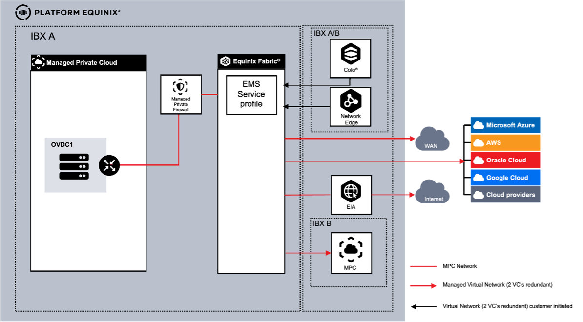
Connectivity Managed Private Firewall
When using the Managed Private Firewall (MPF) as an additional service for extra security including routing and logging, all external connectivity is terminated at the MPF. The MPF is connected to the built-in MPC routing. In this setup of MPF and MPC routing, north-south traffic is first processed by the MPF and then forwarded to MPC, while MPC handles east-west routing within the environment.
This option provides the customer with a highly secure ready for use and built-in routing engine consisting of 2 elements.
- MPF routing configured by Equinix
- MPC routing configurable via the Operational Console
Each MPC internal routed network created is automatically part of the customer routing domain, while internal isolated networks are not.
Networking with Multiple OVDCs
When using multiple OVDCs in a metro, customers can use different Connectivity type combinations. As a Connectivity Type is related to the OVDC. Each scenario comes with different capabilities.
Multiple OVDCs with Connectivity Routed
When using multiple OVDCs in one metro, customers can use different Connectivity Type combinations. As a Connectivity Type is related to the OVDC, each scenario comes with different capabilities.
Multiple OVDCs with Connectivity Routed and Customer Routed
When using multiple OVDCs in one metro, the customer can choose to use a combination of Routed for one OVDC and Customer Routed for the other. Customer will have two options for implementation.
- The OVDCs with connected OVDCs
- The OVDCs are not connected
In the case of scenario 1, there is a VLAN between the Customer Routed and the Routed Gateway. In this scenario customer can create networks between the 2 different OVDCs.
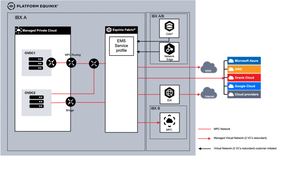
In Scenario 2 where there is no connectivity between the two OVDCs, the OVDCs work as a stand-alone environment.
Connections
The following virtual connection options are supported:
| Connection | # | Type | Description |
|---|---|---|---|
| Equinix Colocation | 1 | Self‑Service VC | Customer‑created and managed connection via the Equinix Fabric Portal using an EMS service profile or service token. |
| Equinix Network Edge | 2 | Self‑Service VC | Customer‑created and managed connection via the Equinix Fabric Portal using an EMS service profile or service token. |
| WAN Providers | 3 | Managed VC | Equinix‑created and managed connection. Part of the MPC order. |
| Cloud Service Providers (CSP) | 4 | Managed VC | Equinix‑created and managed connection. Part of the MPC order. |
| MPC environment in another Metro | 5 | Managed VC | Equinix‑created and managed connection. Part of the MPC order. |
| Equinix Internet Access (EIA) via Equinix Fabric | 6 | Managed Internet Access | Equinix‑created and managed connection. Part of the MPC order. |
Self-Service VC
With a self-service VC, customers initiate VCs via the Equinix Fabric Portal. Equinix Managed Solutions will contact you to configure the connection on MPC side. Each connection requires a pair of VCs to be ordered.
Managed VC
With a managed VC, the VC is part of an MPC order where Equinix initiates the VC configuration. During fulfillment Equinix will contact you for the parameters to configure the VCs.
For both Self-Service and Managed VC, every connection requires two Virtual Circuits for redundancy reasons.
Internet Access
If the customer requires Internet as part of the MPC environment, Managed Internet Access needs to be ordered. Managed Internet Access makes use of Fabric Internet Access (EIA). It is configured with Fixed Bandwidth and no bursting options. EIA supports up to 10 Gbps bandwidth to MPC. IP-spaces need to be ordered as a separate item. For Internet access, customers can also choose to contract a third-party solution with availability on Equinix Fabric. In this case, the customer needs to contract the Internet service themselves.
For third-party internet provider, the customer needs to order two connections for redundancy reasons.
MPC Virtual Networking
The MPC platform offers various virtual network functionalities that a customer can configure in the MPC Operational Console. The following list shows which functions are included as part of the service and which require an additional charge.
| Function | Charge Type | Routed and Managed Firewall | Customer Routed |
|---|---|---|---|
| Standard firewall | Included | Y | N |
| Routing, IPv4 static and dynamic (BGP) | Included | Y | N |
| Routing IPv6 | Included | Y | N |
| NAT | Included | Y | N |
| DHCP | Included | Y | N |
| VPN IPsec Layer‑3 site to site | Included | Y | N |
| Route advertisement | Included | Y | N |
Internal Networks
Internal networks can be created per OVDC via the MPC Operational Console. The MPC Networking service offers a maximum of 1000 internal networks per OVDC. Internal networks can also be configured over multiple OVDCs within the same Equinix IBX when the OVDC is configured with a datacenter group.
There are 2 Internal Networks types:
- Routed allows VMs to be connected to a network that uses the Gateway as the router and give access to the WAN, Colocation, CSPs or Internet and is available to all VMs and vApps within the OVDC.
- Isolated are known as isolated as they aren't connected to a network that has access to WAN, Colocation, CSPs or Internet, unless you attach it to a self-managed router.
Routed networks are only available for Connectivity Type “Routed”.
Datacenter Group
When a customer uses multiple OVDCs, a Datacenter Group will create a single unified network over the different OVDCs so the same network can be used in different OVDCs. If not available, a service request can be raised to configure the Datacenter Group.
Inter Site Networks
When using MPC in different metros, customers can connect 2 MPC sites in different datacenters by requesting a Managed Virtual Circuit between the 2 sites. Based on the Connectivity Type, the network is configured. The connectivity between 2 datacenters is charged as a Managed Virtual Circuit.
Connectivity between more than 2 datacenters is supported but requires a Fabric Cloud Router (FCR), Equinix Fabric IPWAN and 2 Virtual Connections from the MPC Zone and the Fabric Cloud router.
Ordering and configuring Fabric Cloud Router and IPWAN is outside the scope of Managed Solutions.
Purchase Units Connectivity
Units per Single OVDC:
| Purchase Item | UOM | Calculation Type | Description |
|---|---|---|---|
| Connectivity Type | Once | Baseline | Routing instance per OVDC: • Routed • Routed Joined • Customer Routed • Managed Firewall |
| Managed Virtual Circuit | VC | Baseline | Available bandwidth: 10 / 50 / 200 / 500 Mbps or 1, 2, 5, 10 Gbps Two (2) VCs are required per connection for redundancy |
| Managed Internet Access | Each | Baseline | Internet Access available at: 10 / 50 / 100 / 200 / 500 Mbps and 1, 2, 5, and 10 Gbps Managed Virtual Circuits are included in Managed Internet Access. |
| Allocated IP space | Block | Baseline | Supported IPv4 /24 to / 29 and IPv6 Mandatory when Managed Internet Access is procured. |
MPC Operational Console
The MPC Operational Console provides automation tools and an API to manage MPC resources, including the following:
- Manage OVDCs across multiple Equinix data centers
- Create, import, and manage VMs and vApps
- Size VMs (scale up and down)
- Create VM snapshots
- Access VM consoles
- View performance statistics with Operations Manager
- Create and populate the Library with ISO and OVA files
- Direct access to the MPC self-service portal and VM consoles via web browser without VPN requirements
- Extensive options for scripting and automation (API)
- Separate or group VMs for availability or performance
- Manage firewall rules and microsegmentation
- Create and manage routing rules Static and Dynamic for IPv4
- Create and manage routing rules Static for IPv6
- Create and manage NAT, DHCP, and VPN (Layer 2)
- Create and manage VPN IPsec Layer 3 site-to-site tunnels
- Create and manage route advertisements (VRF)
Accessing MPC Flex
To access Managed Private Cloud (MPC), go to the Customer Portal. From there, you can access the following:
- Managed Solutions Portal (MSP) – used to raise tickets, submit service requests, and view MPC usage insights.
- Operational Console – used to manage and operate MPC resources.
Regions
The Operational Console provides access to MPC resources within a specific region. MPC is available in four regions: South America, North America, Europe, and Asia.
Each MPC instance is associated with a region. When an instance exists in a region, you can open its corresponding Operational Console by selecting the regional option from the Managed Solutions area of the Customer Portal.
After you sign in to the appropriate regional console, your access to resources is organized by Organization and Organizational Virtual Datacenters (OVDCs).
Organization
An Organization (Org) represents the customer within the Operational Console. The Org can be viewed as a container for all MPC resources in that region, including virtual data centers, users, and content libraries. The Org name is required when signing in to the MPC Operational Console.
Organizational Virtual Datacenter (OVDC)
An Organizational Virtual Datacenter (OVDC) groups the compute, storage, and networking resources you use to run workloads. A single Org can contain multiple OVDCs, which may differ by IBX location (for example, Amsterdam, London, or Ashburn) or by compute performance profile. If you require additional capacity or an additional OVDC, contact your assigned Service Delivery Manager or Account Manager to request it.
Tenant Roles
The following Tenant Roles apply only to the Managed Private Cloud Single Tenant and Managed Private Cloud FLEX variants.
Tenant roles define the permissions and actions available to users within an MPC tenant. Roles are assigned to users after they are added through the Customer Portal. Roles determine what actions users can perform in the Operational Console and which API capabilities are available to them.
During the initial deployment of a new MPC environment, Equinix creates the first customer administrator account as part of the onboarding process. This account is created using the customer-provided name and email address, and is automatically assigned the Tenant Admin role, which provides full access to the MPC Operational Console, including tenant-level administration and configuration capabilities.
The following roles are supported:
Tenant Admin - The Tenant Admin role provides full administrative access to an MPC tenant. Users assigned this role can manage tenant configuration, user access, and automation capabilities across the environment. Tenant Admin permissions include:
- Access the VM console
- Create and delete snapshots
- Create and delete personal API tokens
- Create, modify, and delete organization-wide service accounts
- Create, modify, and delete virtual machines within the tenant scope
- Create, modify, and delete vApps within the tenant scope
- Create, modify, and delete networks within the tenant scope
- Create, modify, and delete content libraries and library content within the tenant scope
- Configure edge gateways within the tenant scope
- Configure affinity rules
- View tasks and event logs within the tenant scope
Tenant User - The Tenant User role allows users to create and manage workloads and selected resources within an MPC tenant, without access to tenant-wide administrative settings. Tenant User permissions include:
- Access the virtual machines console
- Create and delete snapshots
- Create and delete personal API tokens
- Start and stop virtual machines within the tenant scope
- Start and stop vApps within the tenant scope
- Update VM tools within the tenant scope
- View tasks and event logs within the tenant scope
Tenant Viewer - The Tenant Viewer role provides read-only access to tenant configuration and resource status. Users assigned this role can view the same resources and information available to the Tenant User role, with the following restrictions:
- No create, modify, or delete (CRUD) permissions for virtual machines or vApps
- No Console Access
Managing MPC Flex
User Management
Users of the Operational Console are managed through the Customer Portal. See User and Password management. Once users are added, a Service Request must be submitted to assign the MPC tenant role to the user.
To use a different identity source, identity federation can be configured in the Customer Portal to integrate with an external identity provider. This enables users to sign in using their company credentials.
API Access
Access to the Managed Private Cloud (MPC) Operational Console API is intended for programmatic access and automation. Common automation tools include Terraform, Ansible, Python, and XML- or JSON-based API calls. Authentication to the API requires generating access tokens in the Operational Console. Two access methods are supported, each designed for a different use case.
| Method | Details |
|---|---|
| API tokens | • API access to the Operational Console on behalf of the Customer Portal or federated user accounts for individual programmatic access. • Can be configured by all Customer Portal or federated user accounts. |
| Service accounts | • API access to the Operational Console using standalone accounts intended for organization-wide automation and third-party tools or applications. • Can be configured only by users with the Tenant Admin role. • Can be assigned one of the supported roles. • Supports API access only. |
Terraform Automation
Terraform is an infrastructure-as-code tool that allows cloud and on-premises resources to be defined using human-readable configuration files. These files can be versioned, reused, and shared, enabling a consistent workflow for provisioning and managing infrastructure throughout its lifecycle.
Terraform can be used to manage low-level resources such as compute, storage, and networking. Most Operational Console functionality is available through the API or Terraform. For more information, see the Terraform provider documentation.
API Tokens
API tokens can be created by the Customer Portal or federated user account in the Operational Console and are used for personal programmatic access. Here's how to create an API token:
- Sign in to the Operational Console. Open User preferences from the top-right menu.
- Go to the API Tokens section and select New.
- Enter a name for the token and select Create.
- Copy and store the generated token in a secure location. The token is displayed only once and cannot be viewed again after closing this screen. If the token is lost, a new one must be generated.
- After creation, the token appears in the API Tokens list and can be revoked when no longer needed.
Service Accounts
Service accounts can be created, viewed, and deleted only by users with the Tenant Admin role due to the sensitive nature of these accounts. Here's how to create a service account:
A service account is the owner of any objects it creates in the Operational Console.
- Sign in to the Operational Console. Open Administration, then select Service Accounts and choose New.
- Enter a name for the service account, assign a role, and use the magic wand to generate a unique ID. Select Next to continue.
- (Optional) Assign one or more quota limits to the service account.
- Select Finish to create the service account.
- After creation, the API key is displayed in the Client ID field when viewing the service account properties. Most service account settings can be modified later by selecting Edit.
API Explorer
The API Explorer provides a graphical interface for viewing, testing, and executing API calls and is accessible through the Operational Console.
- In the Operational Console, open the top-right menu and select Help > API Explorer.
- The API Explorer exposes the Swagger‑based JSON API and allows API calls to be executed on behalf of the currently signed-in user account.
Operational Console
When a user is logged into the Customer Portal, the Operational Console can be accessed by navigating to the Managed Solutions Portal, selecting Managed Private Cloud, and then selecting the desired region.
If the Operational Console is accessed directly through its URL and Sign In is selected, the user is redirected to the Customer Portal to authenticate with Customer Portal credentials. The Customer Portal also supports configuration of SAML-based federation with an organization’s identity provider, enabling users to access the Operational Console using their company credentials.
From the Operational Console, actions can be performed to create virtual machines, networks, and security rules.
vApp
A vApp is a group of virtual machines within a virtual data center, for example, representing an application landscape. Virtual machines can be managed as a group, such as taking a snapshot or restarting them, and individual virtual machines can also be managed separately within a vApp. Virtual machines and vApps can be assigned a lease period, after which they are automatically removed. The default lease is set to never expire.
A vApp can be created with or without virtual machines. Creating a vApp without virtual machines can be useful when setting up the vApp network before creating the virtual machines.
Create a new vApp
- Go to the main page under Applications > vApps, select Build New vApp, provide a name and description, and select Build. Wait for the process to complete.
- Options in the vApp window:
- Select Power to turn the vApp on, shut it down, restart it, or pause it. These actions are available only if the vApp contains a virtual machine.
- Select More to add or remove a virtual machine from the vApp.
- Select Details to view or modify additional information.
Virtual Machines
Virtual machines can be created either as part of a vApp or as standalone virtual machines. Creating virtual machines within a vApp is recommended. A vApp can contain up to 100 virtual machines, and virtual machines can be moved between vApps. Networks can also be created between virtual machines that reside in different vApps.
Creating virtual machines as part of a vApp provides several benefits, such as grouping virtual machines by task, function, or retention requirements; configuring startup and shutdown order; improving visibility of network configuration through the vApp network diagram; and enabling delegated management through role-based access.
Allocated storage resources and allocated GB RAM are counted as used storage under the assigned storage policy. When a virtual machine is started, compute resources are deducted from the compute quota of the organization virtual data center (OVDC).
The most common operating system installation method for a new virtual machine includes selecting an ISO file from the private or shared Equinix catalog, allowing the virtual machine to boot from the ISO file when powered on and begin the installation process. Another option is to create a new virtual machine and vApp from an OVF or OVA file on the administrator’s workstation during the creation workflow.
Create a virtual machine
- Go to Applications > Virtual Machines and select Create VM, or select More on a vApp and choose Add VM.
- Follow the steps in the creation dialog, then select OK and wait for the virtual machine to be created.
- Enter a name and computer name.
- Select New for the type.
- Choose whether the virtual machine should start automatically after creation.
- Select the OS family, guest OS, and boot image.
- Configure boot options, including EFI Secure Boot and boot setup.
- Configure Trusted Platform Module (TPM) settings, if required.
- Configure compute resources, including CPU, cores, and memory.
- Configure storage, including storage policy and disk size.
- Configure networking settings.
- In the Virtual Machines screen:
- Select Power to turn the virtual machine on or off, restart it, or pause it.
- Select More to mount installation media, manage snapshots, open the console, or delete the virtual machine.
- Select View to display or modify configuration details and additional settings.
Link installation media from catalog to a VM
If a catalog is already available and installation media has been uploaded, it can be attached to the virtual machine.
- Locate the virtual machine and select More.
- Select Insert Media and choose the installation file. The file is connected as a virtual CD-ROM.
- After the job completes, it is recommended to detach the installation file by selecting Eject Media.
VM Console
A virtual machine can be managed through the Operational Console. Two console types are available:
- Web Console which works from your browser.
- VM Remote Console which requires installing a plug-in.
Installation media (ISO) cannot be used directly from a local device. Media must be uploaded to a catalog before it can be mounted to a virtual machine.
The VM Remote Console plug-in for Windows devices is available in the shared catalog. For macOS and Linux (including Windows via Workstation), VMRC functionality is included in VMware Fusion Pro and VMware Workstation Pro. These applications require separate licensing and are not included with MPC or provided by Equinix.
- Locate the virtual machine from the vApp or the Virtual Machines overview.
- Select More and choose the desired console type: the Web Console (no plug-in required) or the VM Remote Console (plug-in required).
Snapshots
A snapshot captures the state of a complete virtual machine or vApp before an action is performed. The Operational Console allows only one snapshot at a time, with or without the active memory state. Taking a snapshot temporarily doubles the storage usage of the virtual machine or vApp. Snapshots can affect virtual machine performance. It is recommended to retain snapshots for a maximum of 2-3 days; snapshots older than one week are removed automatically. For longer-term preservation of a virtual machine state, create a clone or perform a backup of the virtual machine or vApp.
- Locate the virtual machine or vApp, select Actions > Snapshot, and choose Create Snapshot, then confirm.
- To restore the virtual machine to the snapshot state, select Revert to Snapshot and confirm.
- To delete the snapshot, select Remove Snapshot and confirm.
When a new snapshot is created from a VM with an existing snapshot, the old snapshot is removed. To have access to all snapshot options, VMware Tools must be installed on the VM.
Catalogs
The catalog in the Operational Console stores vApps, virtual machines, and media files (such as ISO images). Equinix provides a shared catalog with a set of ISO files. The shared catalog is associated with the OVDC, specifically the environment's metro.
A private catalog can also be created to store installation media or templates. Files can be uploaded directly, or templates can be created from existing virtual machines or vApps. Files stored in the private catalog count toward the OVDC storage quota. All uploaded software must comply with vendor licensing requirements and Equinix policies. The catalog may be used only for ISO and OVF files.
Create a catalog
To store installation media or templates, a catalog must first be created.
- On the home screen, select the menu icon (three horizontal lines).
- In the Content Hub screen, select Catalogs, then choose New.
- Enter a name and description for the catalog. Catalogs can be stored on any available storage profile. By default, the fastest profile is selected. To choose a specific storage profile, enable Pre-provision on a specific storage policy, select the ORGOVDC, and choose the required storage policy.
Add installation media
When the catalog is available, installation media can be uploaded to it.
- Go to Content Libraries > Media & Other and select Add.
- In the new screen, select the catalog, click the upload icon (arrow pointing up) to open the file browser. Select the installation file and confirm with OK.
- Edit the name if required and select OK to start the upload. In the Media & Other overview, a rotating indicator appears while the upload is in progress. A green check mark appears when the upload is complete. The file is then ready for use.
- Selecting the three dots next to the file name provides options to delete the file or download it to the workstation.
Create a vApp Template
A vApp template can be created by uploading a file from a local workstation or by using an existing vApp. A template for a single virtual machine based on a vApp can only be created if the vApp contains exactly one virtual machine.
- Locate the vApp to be used as the source, select More, and choose Add to Catalog. Select the destination catalog and enter a name. An exact copy can be created, or virtual machine settings can be adjusted if VMware Tools are installed before template creation.
- To access the vApp template, go to Content Hub > Catalogs and open the relevant catalog. Once available, the template can be used to deploy new virtual machines.
Shared Catalogs
Equinix provides a shared catalog (OS-CATALOG-1) per MPC metro that contains a set of operating system variants. Select the catalog associated with the metro where the virtual machine is deployed. The shared catalog is associated with the MPC variant (FLEX or ST) in that metro. If both MPC FLEX and MPC ST are used in the same metro, two catalogs for that metro are visible.
Connectivity and Networks
The Operational Console provides several options for connecting and accessing services within the organization or externally. Depending on the selected connectivity model, an OVDC is created with either Bridging (MPC Connectivity Customer Routed in the order) or Routing (MPC Connectivity Routed in the order).
The available network functions in the Operational Console vary depending on whether Customer Routed or Routed connectivity is selected. In the Operational Console, two types of networks can be created through Self-Service:
- Isolated network (internally connected): An isolated network exists only for virtual machines within the OVDC.
- Routed network (externally connected): A routed network provides access to external networks outside the OVDC through the Edge Gateway.
| MPC Connectivity Type | Isolated | Routed |
|---|---|---|
| Bridging | Yes | No |
| Routing | Yes | Yes |
MPC Gateway Firewall Architecture
MPC uses a gateway firewall architecture to secure traffic entering and leaving the environment. Firewall controls are applied at the perimeter to regulate external access and protect MPC resources. The Gateway Firewalls (North–South) protect the MPC perimeter and handle traffic entering or leaving the environment.
Create an isolated OVDC Network
An organization virtual data center (OVDC) network enables virtual machines (VMs) to communicate with each other and, optionally, with external networks. A single OVDC can contain multiple networks.
- In the Operational Console Virtual Datacenters dashboard, select the OVDC where the network is created.
- In the left navigation panel, select Networks.
- Click New.
- Under Scope, select the current OVDC for the isolated network.
- In the Network Type page of the New Organization VDC Network dialog box, select Isolated, then click Next.
- In the General page, enter a Name and Description for the network.
- In the Gateway CIDR field, select the IP space for the network from the dropdown list. This list is pre-populated by Equinix based on customer input during deployment.
- Dual Stack can be enabled when IPv6 is required.
- Guest VLAN Allowed can be enabled to permit multiple VLANs within connected VMs.
- Click Next.
- (Optional) In Static IP Pools, enter a range of IP addresses for VMs on this network and click Add. This allows the Operational Console to automatically assign IP addresses during VM creation. If not configured, IP assignment must be done manually during VM creation. Example: If the gateway address is 192.168.1.1/24, a static IP pool of 192.168.1.10–192.168.1.100 provides 91 usable IP addresses. Additional ranges can be added later if needed.
- When finished, click Next.
- (Optional) In the DNS page, enter DNS information, then click Next. If omitted, DNS settings must be entered manually when creating VMs.
- On the Ready to Complete page, review all settings and click Finish.
Create a routed OVDC Network
A routed OVDC network enables virtual machines (VMs) to communicate with each other and with external networks using Layer 3 (L3) routing. A single OVDC can contain multiple routed networks.
- In the Operational Console Virtual Datacenters dashboard, select the OVDC where the network is created.
- In the left navigation panel, select Networks, then click New.
- Under Scope, select Current Organization Virtual Data Center.
- In the Network Type page of the New OVDC Network dialog box, select Routed, then click Next.
- Under Edge Connection, select the Edge Gateway that the routed segment will connect to.
- In the General page, enter a Name and Description for the network.
- In the Gateway CIDR field, select the IP space for the network from the dropdown list. This list is pre-populated by Equinix based on the customer inputs provided during deployment.
- Enable Dual Stack if IPv6 is required.
- Enable Guest VLAN Allowed to permit multiple VLANs within connected VMs.
- Click Next.
- (Optional) In the DNS page, enter DNS settings, then click Next. If not configured here, DNS information must be added manually during VM creation.
- On the Ready to Complete page, review the selections then click Finish. After the network has been created and connected to the OVDC, the Edge Gateway can be configured to control which traffic is allowed into and out of the OVDC.
Guest VLAN Allowed
Enabling this option allows VLAN tags (802.1Q TAGs) to be configured on the network interfaces of virtual machines. This allows multiple VLANs to be operated on the same routed or isolated network segment.
Create Gateway Firewall Rules
The Operational Console provides a fully featured Layer 4 firewall to control traffic moving across security boundaries—both North-South (traffic between the OVDC and external networks) and East-West (traffic within and between OVDC networks). When specifying networks or IP addresses for firewall rules, the following formats are supported:
- A single IP address
- IP ranges (e.g., 192.168.1.10–192.168.1.50)
- CIDR notation (e.g., 192.168.2.0/24)
- Keywords: internal, external, or any
- In the Operational Console Virtual Datacenters dashboard, select the OVDC containing the Edge Gateway where the firewall rules are created.
- In the left navigation panel, click Edges. The available Edge Gateways will appear on the right.
- Select the Edge Gateway to configure, then open the Firewall tab.
- In the Firewall tab, firewall rules can be created and managed.
- Click New to add a new rule. For the new rule, specify the following fields:
- Name
- Applications
- Context
- Source (IP address, IP sets, Static Groups)
- Destination (IP address, IP sets, Static Groups)
- Action (Allow, Drop, Reject)
- Protocol (IPv4, IPv6, or both)
- Logging
- Comments
- In the Source and Destination fields, define the addresses for the rule. To specify an IP or range, click IP and enter the Value, then click Keep. To reuse groups of IPs, go to Grouping Objects and click + to create an IP Set. This IP Set can then be selected for multiple rules.
- In the Application field, click + then in the Add Service dialog box, specify the Protocol, Source Port and Destination Port. Or define a custom protocol/port combination. When done, click Keep. Custom applications can also be created in advance and applied to firewall rules.
- Choose whether the rule’s Action is Accept (Allow) or Deny (Drop/Reject). If a syslog server is configured, select Enable logging.
- Click Save changes to finalize the rule.
An example of a firewall rule is to allow HTTPS traffic from the internet. This example uses allocated public IP addresses. The source is any (any IP address within the OVDC). The source port is also any. The destination is a private IP address and the destination port is 443 for HTTPS. For this to work you need a DNAT configuration.
Create NAT Rules
Network Address Translation (NAT) allows the source or destination IP address to be changed so that traffic can pass through a router or gateway. The most common types of NAT on the Edge Gateway are:
- Destination NAT (DNAT) - changes the destination IP address of the packet.
- Source NAT (SNAT) - changes the source IP address of the packet.
Other options are:
- NO DNAT
- NO SNAT
- REFLEXIVE
For a virtual machine (VM) to access an external network resource from its OVDC, NAT may be required in certain use cases. In these cases, use one of the following options:
- Public internet IP addresses provided by Equinix.
- Private networks via MPC Connect.
- This functionality is primarily applicable when the Edge Gateway is configured with public IP addresses and VMs are using private IP addresses.
- NAT rules function only when the firewall is enabled. The firewall should remain enabled at all times.
DNAT changes the destination IP address of a packet and performs the reverse operation for reply traffic. DNAT can be used to expose a service running on a private network through a public IP address.
- In the Operational Console Virtual Datacenters dashboard, select the OVDC that contains the Edge Gateway where the DNAT rule is created.
- In the left navigation panel, click Edges. Select the NAT tab and add a new NAT rule.
- In the NAT section, click + DNAT Rule.
- In NAT Action, select the type of NAT rule.
- Enter an External IP (for example, 10.30.40.95).
- Enter an External Port (for example, 443).
- Enter an Internal IP (for example, 192.168.1.10).
- Advanced Settings
- State - enables or disables the rule
- Logging - logs the rule
- Priority - lower values mean a higher priority while 0 is the default value
- Firewall Match
- Match Internal Address
- Match External Address
- Bypass
- Applied To - leave blank
- If a syslog server is configured, select Enable logging.
- When finished, click Keep, then Save changes.
Create SNAT Rules
SNAT changes the source IP address of a packet and performs the reverse operation for reply traffic. When accessing external networks, such as the internet, an SNAT rule is required to translate internal IP addresses to an address available on the external network.
- In the Operational Console Virtual Datacenters dashboard, select the OVDC that contains the Edge Gateway where the SNAT rule is created.
- In the left navigation panel, click Edges. Select the NAT tab and add a new NAT rule.
- In the NAT section, click + SNAT Rule.
- In NAT Action, select SNAT.
- External IP - the external network (usually named VCD_CUSTOMER_WAN).
- Internal IP - the network or IP address translated for internet access.
- Advanced Settings
- State - enables or disables the rule
- Logging - logs the rule
- Priority - lower values mean a higher priority while 0 is the default value
- Firewall Match
- Match Internal Address
- Match External Address
- Bypass
- Applied To - leave blank
- When finished, click Keep, then Save changes.
Create NO SNAT Rules
NO SNAT rules negate existing SNAT rules. A NO SNAT rule can be created to bypass SNAT for traffic destined for a specific IP address. To ensure correct processing order, the NO SNAT rule must be assigned a higher priority (lower numerical value) than the SNAT rule. The default priority is 0, which is the highest priority.
- In the Operational Console Virtual Datacenters dashboard, select the OVDC that contains the Edge Gateway where the NO SNAT rule is created.
- In the left navigation panel, click Edges. Select the NAT tab and add a new NAT rule.
- In the NAT section, click + No SNAT Rule.
Configure IPsec VPN
Operational Console supports the following types of site-to-site VPN connections:
- An Edge Gateway within the same organization
- An Edge Gateway in another organization (Equinix or another vCloud service provider)
- A remote network that provides an IPsec VPN endpoint, such as a cloud service provider or a colocation environment
Depending on the connection type, IP addressing must be configured for both endpoints, along with a shared secret. The OVDC networks that are permitted to communicate over the VPN connection must also be specified.
Before configuring IPsec VPN settings, take note of the IP address of the Edge Gateway to be used as the tunnel endpoint.
- In the Operational Console Virtual Datacenters dashboard, select the OVDC that contains the Edge Gateway to be configured.
- In the left navigation panel, click Edges.
- On the Edges page, select the Edge Gateway.
- In the Services tab, locate the IPsec VPN option and click New to create a new IPsec VPN configuration.
Configure the Edge Gateway IPsec VPN Settings
- Configure a name, enable Login to view logs, and leave the remaining options set to their default values.
- Peer Authentication Mode
- Pre-Shared Key: The shared secret used to authenticate and encrypt the connection. It must be an alphanumeric string between 32 and 128 characters and include at least one uppercase letter, one lowercase letter, and one number. This value must be the same on both sites.
- Certificate: To use a certificate, upload the certificate and the CA certificate.
-
Endpoint Configuration
Local Endpoint
- IP Address: The external IP address of the Edge Gateway.
- Networks: Enter the organization networks that can access the VPN. Separate multiple local subnets with commas.
Remote Endpoint
- IP Address: The external IP address of the remote site, on‑premises firewall, or edge gateway where the VPN is configured.
- Networks: The subnet on the on‑premises network that should be accessible from the OVDC. For example, if on‑premises networks use the 172.20.0.0/16 range, enter 172.20.0.0/16, or a smaller subnet such as 172.20.0.0/25.
- Remote ID:
- This value uniquely identifies the peer site and depends on the tunnel authentication mode. If not specified, the remote ID defaults to the remote IP address.
- Pre-shared Key: The remote ID depends on whether NAT is configured. If NAT is configured on the remote ID, enter the private IP address of the remote site. Otherwise, use the public IP address of the remote device terminating the VPN tunnel.
- Certificate: The remote ID must match the SAN (Subject Alternative Name) of the remote endpoint certificate, if present. If the remote certificate does not include a SAN, the remote ID must match the distinguished name of the certificate used to secure the remote endpoint.
-
When configuration is complete, click Keep to create the edge end of the VPN tunnel, then click Save changes.
Create the Second VPN Gateway
If this endpoint is in a different OVDC, repeat the steps to create the tunnel. After the tunnel is created, update firewall settings and validate the connection. If connecting to an external data center, configure the tunnel on those premises.
IKE Phase 1 and Phase 2
IKE (Internet Key Exchange) is a standard mechanism for establishing secure, authenticated communications. The following lists the supported configuration parameters for Phase 1 and Phase 2.
Phase 1 parameters
Phase 1 establishes peer authentication, negotiates cryptographic parameters, and generates session keys. Supported Phase 1 parameters are:
- Main mode
- AES/AES256/AES-GCM (user configurable)
- Diffie-Hellman group
- Pre-shared secret (user configurable)
- SA lifetime of 28800 seconds (eight hours), with no kbytes rekeying
- ISAKMP aggressive mode disabled
Phase 2 parameters
IKE Phase 2 negotiates the IPsec tunnel by generating keying material, either by deriving it from the Phase 1 keys or by performing a new key exchange. Supported Phase 2 parameters are:
- AES/AES256/AES-GCM (matches the Phase 1 setting)
- ESP tunnel mode
- Diffie-Hellman group
- Perfect forward secrecy for rekeying (only if enabled on both endpoints)
- SA lifetime of 3600 seconds (one hour), with no kbytes rekeying
- Selectors for all IP protocols and all ports between the two networks, using IPv4 subnets
Configure the Edge Gateway Firewall for VPN
After the VPN tunnel is established, create firewall rules on the Edge Gateway for traffic passing over the tunnel.
- Create firewall rules for both traffic directions: data center to OVDC and OVDC to data center.
- For data center to OVDC, set:
- Source to the source IP range of the external OVDC or data center network
- Destination to the destination IP range of the OVDC network
- For OVDC to data center, set:
- Source to the source IP range of the OVDC network
- Destination to the destination IP range of the data center or VDC network
Validating the tunnel
After both ends of the IPsec tunnel are configured, the connection should establish automatically.
To verify tunnel status in the Operational Console:
- On the Edges page, select the edge to configure and click Configure Services.
- Select the Statistics tab, then select the IPsec VPN tab.
- For each configured tunnel, a tick indicates that the tunnel is operational. If a different status is displayed, review the tunnel configuration and firewall rules.
- Traffic can now be sent over the VPN.
After the tunnel is established, it can take up to two minutes for the VPN connection to be shown as active.
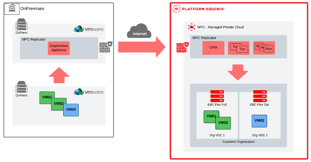
Disaster Recovery and Migration with MPC Replication
MPC Replication is MPC’s Disaster Recovery-as-a-Service (DRaaS) solution. Fully integrated into the MPC portal, it enables asynchronous replication between MPC multi-tenant and on-premises VMware environments. The Availability service can migrate, protect, fail over, and roll back vApps and virtual machines.
MPC Replication features a unified architecture for disaster recovery and workload migration. With this solution, organizations will be able to migrate and protect vApps and virtual machines directly from the MPC portal:
- Onboarding and Migration-as-a-Service
- Hybrid Cloud to Hybrid Cloud Disaster Recovery-as-a-Service
Solution Architecture
MPC Replication requires the existing installation of VMware Cloud Director to be fully operational. This means that the VCD must be ready to provide compute resources to tenants through OrgVDC organizational virtual datacenters. The MPC Replication concept consists of the following set of appliances:
- One Cloud Manager Appliance - CRM
- One Cloud Replication Tunnel - TUN
- One Cloud Replicator - REP
In the on-premises datacenter, a single appliance is deployed and configured to replicate or migrate virtual machines running on vCenter Managed Infrastructure.
Use Cases
MPC Replication supports two different use cases, Disaster Recovery and vApps/VM Migration. In both cases, the MPC will always be the replication target, and the source can be another MPC site or an on-premises VMware vSphere environment with vCenter. MPC Replication cannot protect or migrate bare metal servers or VMs managed by non-VMware hypervisors.
Disaster Recovery
Disaster Recovery-as-a-Service DRaaS, provides the service of protection of your virtual machines that are running in a productive datacenter, having the possibility of replicating this workload to a virtual datacenter (OrgVDC) of the MPC, which can target a Flex or Single modality.
Using synchronization parameters, with default SLA Profile definition, it will be possible to change RPO, Point-in-time, retention, bandwidth settings.
There are also settings that control how the VM will be configured after failover – which network each network adapter will connect to, choose how to configure the IP address of each network interface, and more.
After replication is configured and the initial synchronization is finished, there are different operations that can be performed on each protection domain:
- Manual Sync - The administrator can initiate a manual synchronization outside the configured RPO window.
- Test Failover - Used to test a vApp/VM from the replicated data and binding to the target site in isolation, keeping the source VM operational. This operation is followed by a cleanup process, removing all VMs created during testing on the target. Keeping replications operational even in the test period.
- Failover - Used when the source site is down. On the target side, the VM is constructed and powered ON from the replicated data.
- Reverse - After a successful failover to the destination side and when the source side is up and running again, the customer can decide to roll back the replication direction of the original target and perform a new scheduled failover, returning the environment to its original state.
- Migrate - Used when both sides are operational. When this operation is initiated vApp/VM at source side is powered off, in destination new vApp/VM is constructed from replicated data and is powered on.
Migration
When the customer intends to do the planned migration of workloads to the MPC, they can use the migration workflow, which simplifies the process. When a new migration is configured, MPC Replication initiates a vApp/VM replication from the source to the destination. When synchronization is complete, the source VM is powered off and any deltas generated at the source site are synchronized with the destination. At the destination side, the MPC Replication requests from VCD to construct a new vApp/VM from replicated data and powers it on. Migrated workloads could be customized to make them ready for operation in the new virtual datacenter. As with the disaster recovery use case, migration can be configured for groups of multiple vApps/VMs.
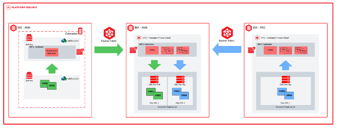
Use Case Topology
On-Premises to MPC:
On-Premises from Equinix to MPC or MPC to MPC:
Accessing the MPC Replication Services
To access the MPC Replication service, on the MPC portal, select the Availability (“Site”) submenu, in the More tab.
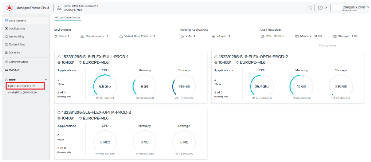
The dashboard displays Incoming VMs, which are virtual machines being replicated to the current site, and Outgoing VMs, which are virtual machines being replicated from the current site to another site.
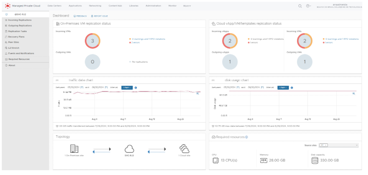
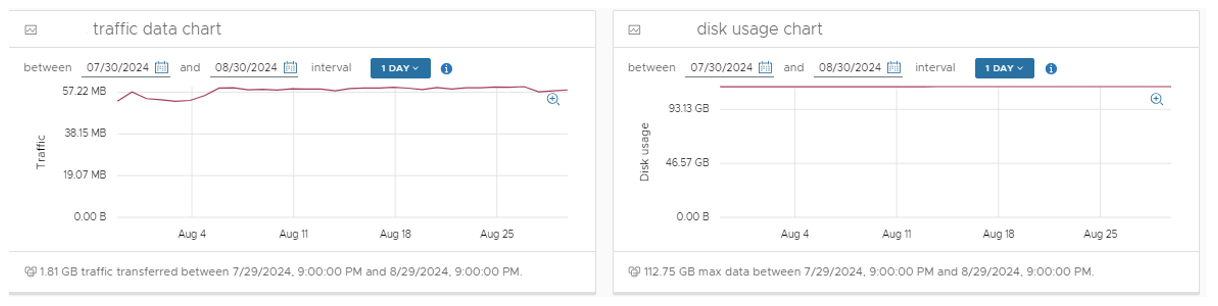
Use the Traffic Data graph to filter and view the amount of replication traffic transferred, measured in GB. Use the Disk Usage graph to view the amount of storage, measured in GB, consumed by replicated workloads at the current site.
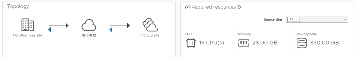
The dashboard provides a summary of the replication topology and displays the compute and storage resources required to support replication, including vCPU, memory, and virtual disk (vHD) capacity.
If the necessary resources are not available, replication will continue, but the virtual machine might not be able to power on during a disaster recovery event.
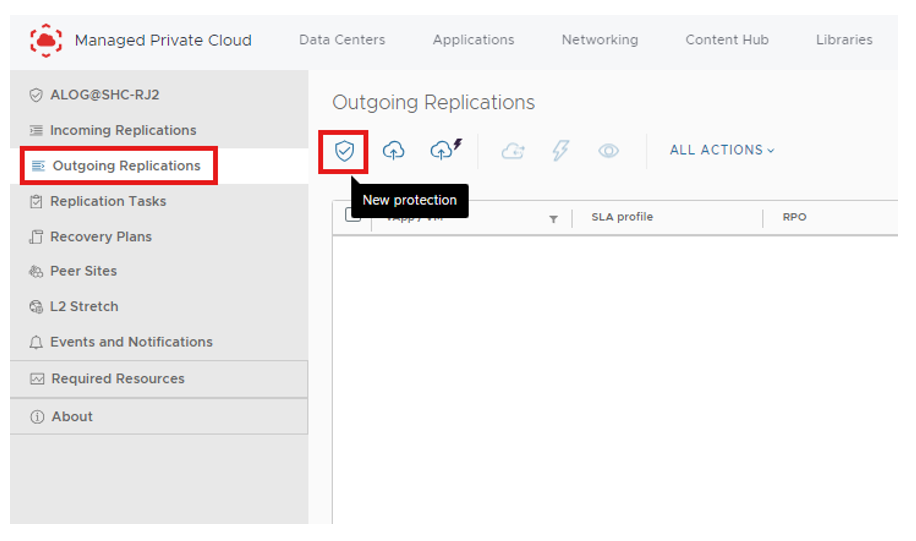
Setting Up a New Replication (DR Feature)
On the Replication service home screen, configure Inbound and Outbound replications. To replicate data from the logged-in site to a target site, select New Protection from the Outbound Replications menu.
Just like Outbound Replication, Inbound Replication is configured through the Replication service home screen.
You will need to authenticate on the destination website. To do this, you will need to generate a new challenge as shown below. Enter the Organization Name and click GENERATE NEW CHALLENGE.
Service Options
MPC Flex includes several service options that can be ordered separately.
VM Replication for Disaster Recovery
MPC Disaster Recovery is a self‑service option that provides crash‑consistent VM replication using three customer‑selectable SLA profiles. It supports replication between FLEX and ST deployments, including mixed configurations. The secondary datacenter VDC may use lower‑capacity compute or storage, provided it is sufficient for the expected workload.
For disaster recovery to succeed, the VDC and network topology must support connectivity to the internet, on‑premises locations, or a cabinet in the secondary datacenter. Self‑service testing of VM failovers is supported to verify that failover behavior meets requirements.
To configure the service, virtual machines can be assigned to an SLA profile in the Operational Console. When replication is activated, VM data is replicated to the selected secondary VDC.
MPC Disaster Recovery provides the following SLAs:
| Parameter | Value | Description |
|---|---|---|
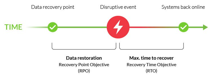
| RPO | Gold: 1 hour Silver: 4 hours Bronze: 24 hours | Timeframe in which the replication is finished. |
| RTO | 30 minutes | Timeframe within which the VM must be started in the secondary datacenter after customer‑initiated failover. RTO starts after failover is initiated by customer. |
| # Retention points | Gold: latest + 8 points Silver: latest + 6 points Bronze: latest + 2 points | All profiles consist of the latest restore point plus a defined number of automatically stored restore points. Maximum restore point age is 2 days. |
The disaster recovery feature uses I/O filter-based capture technology. This approach avoids performance impact associated with snapshot-based replication.
Failover
When a failover is required, the customer can initiate the failover of workloads to the secondary datacenter through the Operational Console. Virtual machines are replicated according to the selected SLA profile, and the replication networks are operated and monitored by Equinix as part of the service.
Customer-related connectivity, including VM and application attachment, is outside the scope of the MPC Disaster Recovery option and must be prepared in advance to ensure connectivity between datacenters, the internet, cabinets, and on‑premises locations.
When the primary datacenter becomes operational again, the customer reverses the replication direction in the Operational Console. After replication is restored, VMs and applications can be moved back to the primary datacenter at a suitable time chosen by the customer.
Responsibilities
Responsibilities for effective disaster recovery include understanding which activities affect performance and capacity, and how they are divided between Equinix and the customer.
| Activities | Equinix | Customer |
|---|---|---|
| Selecting suitable MPC compute and storage for the DR site | I | RAC |
| Making the selected SLA profile available in the Operational Console | I | RAC |
| Configuring disaster recovery in the Operational Console | I | RAC |
| Ensuring DR site capacity is sufficient for disaster recovery | I | RAC |
| Managing replication infrastructure and connectivity | RAC | I |
| Configuring customer connectivity and networks during failover | I | RAC |
Purchase Units
The MPC disaster recovery feature is procured on a VM per month basis depending on the chosen SLA Profile as Service Option of the Primary Datacenter, pricing includes the replication connectivity and bandwidth. Costs for compute and storage capacity in the secondary datacenter is part of the MPC Service. Multi-site networking connectivity for VMs is additionally required.
| Purchase Item | Tier | UOM | Calculation Type | Description |
|---|---|---|---|---|
| Service Option – Disaster Recovery | Bronze Silver Gold | VM | Baseline Overage | Replication of a VM to a selected secondary MPC VDC in another datacenter, according to the selected SLA. |
Metering
To determine the amount of replicated VMs for billing, all VMs are counted that were part of a certain SLA Profile on a per day basis. If a VM is changed between different SLA Profile within a month, it is billed accordingly.
Relations and Dependencies
- MPC Disaster Recovery is available only with MPC Flex and/or MPC ST.
- The service option requires two MPC VDCs in different datacenters.
- The service option is available only for selected datacenter combinations.
Backup and Restore
Backup and Restore for MPC resources are provided through the Managed Private Backup Service, which is ordered separately. The service includes backup of VM data or application data.
Software Catalog
A Software Catalog is available in the self-service portal. The catalog lists software that can be used in VMs running in OVDCs and includes both open-source and licensed software. The licensed software catalog includes Microsoft SPLA - Windows Server.
Software Licensing Purchase Units
| Purchase Unit | Type | Charge Type | UOM | Ordering and Billing |
|---|---|---|---|---|
| Windows Server per vCPU | Standard | Baseline and Overage | vCPU | Baseline and Overage model per vCPU for the vCPUs of VMs that are powered on. |
In addition to the catalog, software licenses can be ordered through the Equinix Software License Service.
Bring Your Own License
Bring Your Own License allows customers to use existing software licenses, subject to validation of vendor licensing terms, with customers remaining fully responsible for compliance with all software vendor licensing requirements.
Support Plan
The Support Plan provides additional services, including service requests, enhanced support, reporting, and design assistance
- The Managed Solutions Premier Support Plan is a prepaid program offering monthly or annual (one-time payment) support hour blocks at a discounted rate.
- Support time is calculated in 15-minute increments.
- Without a prepaid plan, support is charged per hour at the Premier Support Service standard rate, calculated in 15-minute increments.
| Purchase Unit | Type | Charge Type | UOM | Ordering and Billing |
|---|---|---|---|---|
| Technical Support Plan | Monthly | Baseline | Hour | Monthly reservation of hours for technical support |
| Technical Support Plan | Annual | Baseline | Hour | Yearly reservation of hours for technical support |
The Support Plan applies to all Managed Solutions products, not to one specific product.
If all the hours from the plan are consumed, additional hours are charged at the Premier Support Service per hour rates (standard hourly rate).
Monthly or prepaid Managed Solutions Premier Support Plan hours do not roll over and are forfeited if not used. Prepaid Managed Solutions Premier Support Plan usage beyond the pre-purchased allotted amount is billed at regular Premier Support Service rates unless an upgrade is requested.
The plan is country specific and cannot be linked to a specific IBX data center.
Migration Support
To migrate customers workloads from On Premises to MPC, Equinix provides migration tooling that makes it possible to migrate workloads in Self Service without refactoring the applications. The tooling supports VMware workloads from vSphere or Cloud Director. To get started, customers receive an appliance that can be installed in their VMware environment and be paired with their MPC environment. The tooling uses asynchronous replication to transfer workloads.
By default, migrations are performed over the public internet. Upon request, a private connection can be created over Equinix Fabric. Charges for Fabric connectivity are billed separately through the Fabric service. For migration over Fabric, existing Virtual Circuits cannot be used, dedicated Virtual Circuits must be provisioned specifically for the migration. Over internet speeds up to 400Mbps while for a Fabric connection speeds up to 10Gbps are supported.
The migration tooling is provided free of charge. Additional support can be requested via the Support plan. After the migration has been completed the tooling is disabled.
| Connection | Speed | Network Configuration |
|---|---|---|
| Internet | Up to 250 Mbps | No |
| Fabric | Up to 10 Gbps | Yes, set up VLANs |
Service Demarcation and Enabling Services
With MPC, Equinix provides an Infrastructure‑as‑a‑Service platform that includes datacenter facilities, datacenter networking, compute, storage, and virtual networking. Equinix manages the service up to the hypervisor level and provides the platform licensing for virtualization. Resources are delivered in a logically separated environment, and an Operational Console is available for customers to manage their environment.
Customers are responsible for managing their own workloads. This includes creating and managing virtual machines, storage, virtual networks, security policies, and capacity, as well as providing the required licenses for operating systems and applications.
MPC Flex is a managed service with limitations on self-service access and functionality to maintain performance, availability, and security.
Access
- Access to vSphere or vCenter functionality is available only through the MPC Operational Console and APIs.
- Integration with vCenter and vSphere is limited to the functionality exposed through the MPC Operational Console.
Compute
- Creating VM snapshots is limited to a single concurrent snapshot per VM.
Virtual disks
- Moving virtual disks between VMs through the MPC Operational Console or APIs is not supported; a support ticket must be created through the Equinix support desk.
- Sharing a virtual disk between multiple VMs is not supported; Microsoft Windows Server Failover Clustering (WSFC) with shared disks is not supported.
Network
- Single Root I/O Virtualization (SR-IOV) and direct physical NIC access from VMs are not supported.
Purchase Units
The MPC service is charged monthly based on Baseline values or Baseline with Overage charge types.
- Baseline - The specific volume of the service unit of measure as defined in the order.
- Overage - The quantity of the service consumed that exceeds the contracted Baseline volume.
Catalog of Purchase Units
The table lists the purchase units for Managed Private Cloud, including unit of measure and billing method:
| Category | Purchase Unit | UOM | Install Fee | Billing Method | Overage |
|---|---|---|---|---|---|
| MPC Service | Connectivity – Routed | Each | Baseline | ||
| Connectivity – Customer Routed | Each | Baseline | |||
| Connectivity – Managed Firewall | Each | Baseline | |||
| Connectivity – Joined | Each | Baseline | |||
| MPC Compute | vCPU – Full | vCPU | Baseline | Yes | |
| vCPU – Optimized | vCPU | Baseline | Yes | ||
| MPC Memory | vRAM | GB | Baseline | Yes | |
| MPC Storage | High Performance | TB | Baseline | Yes | |
| Performance | TB | Baseline | Yes | ||
| MPC Service Option | Network – Managed Virtual Circuit (xx Mbps) | Each | Yes | Baseline | |
| Network – Managed Internet Access (xx Mbps) | Each | Baseline | |||
| Network – Additional IP space /24/25/26/27/28/29 | Each | Baseline | |||
| Network – External network | Each | Yes | Baseline | ||
| License – Windows Server per vCPU | vCPU | Baseline | Yes | ||
| Disaster Recovery Gold/Silver/Bronze | VM | Baseline |
Calculation of Overage Values
The consumption of MPC is measured multiple times a day. Every day the maximum used consumption of that day is used for the Overage calculation. The Overage value for billing is calculated as the sum of the day values divided by the number of days of that month.
The number of days in a month is calculated as the number of days between the fore last day before the start of the month until the fore last day in the next month. For example, the Overage for October is based on consumption from 29 September to 30 October. In this example the Overage for billing for this month is 1110/30 = 37.

Roles and Responsibilities
During service fulfillment and delivery, responsibilities are shared between Equinix and the customer. The following section provides an overview of these responsibilities.
Onboarding
| Activities | Equinix | Customer |
|---|---|---|
| Schedule / execute project kickoff meeting | RA | CI |
| Schedule / execute customer onboarding | RA | CI |
| Delivery of the OVDC in accordance with the order | RA | I¹ |
| Delivery of the agreed compute capacity in accordance with the order | RA | I¹ |
| Delivery of the agreed storage capacity in accordance with the order | RA | I¹ |
| Delivery of the connectivity type in accordance with the order | RA | I¹ |
| Delivery of the Managed Virtual Circuits in accordance with the order | RA | C |
| Delivery of the Managed Internet Access in accordance with the order | RA | C |
| Delivering the agreed network functionality in accordance with design (optional) | RA | C |
| Delivery of the MPC Operational Console | RA | I¹ |
| Delivery of the admin account for the Operational Console | RA | I¹ |
Acceptance into Service
After onboarding activities are completed, testing activities confirm that the product has been delivered successfully and is ready for billing.
| Activities | Equinix | Customer |
|---|---|---|
| Test access to MPC product page on Managed Solutions Portal | CI | RA |
| Test access to MPC documentation on docs.equinix.com | CI | RA |
| Test access to MPC operational console | CI | RA |
| Confirm MPC fulfillment based on preview evidence | CI | RA |
| Set product as enabled for customer on internal systems | RA | I |
Operational
After Managed Private Cloud is enabled for customers, the following operational items apply:
| Activities | Equinix | Customer |
|---|---|---|
| Technical management of the service (overall) | RAC | I¹ |
| Functional management of the customer environment within the service (overall) | I² | RAC |
| MPC infrastructure monitoring and maintenance | RA | I |
| Create, import, and manage VMs and vApps | I² | RAC |
| Scale VMs up and down | I² | RACI |
| Manage VM snapshots | RACI | |
| Manage access to VMs with console | RACI | |
| Request performance statistics | RACI | |
| Create and fill Library with customer’s own ISO/OVA files | RACI | |
| Separate or group VMs for availability or performance | I² | RAC |
| NFV: Virtual L2 networks | I² | RAC |
| NFV: Standard firewalling | I² | RAC |
| NFV: Routing (static) | I² | RAC |
| NFV: Routing (dynamic OSPF / BGP) | I² | RAC |
| NFV: NAT | I² | RAC |
| NFV: DHCP | I² | RAC |
| NFV: Load balancing | I² | RAC |
| NFV: VPN (IPsec, Client) | I² | RAC |
| Setup and manage scripting and automation capabilities | RACI |
RACI stands for Responsible, Accountable, Consulted and Informed.
- Informing is only mandatory for tasks that have an impact on the functioning of the user environment.
- Informing is only required for tasks that have an impact on the operation and/or management of the service.
Incident Management
Incident Management is included as part of service support. All incidents are handled based on priority. Priority is determined after an incident is reported and assessed by Equinix based on the information provided.
| Priority | Impact / Urgency | Description |
|---|---|---|
| P1 High | Unforeseen unavailability of a service or environment delivered and managed by Equinix, in accordance with the service description, due to a disruption. The user cannot fulfil its obligations toward its users. The user suffers direct demonstrable damage due to the unavailability of this functionality. | The service must be restored immediately; the production environments are unavailable, with platform‑wide disruptions. |
| P2 Medium | The service does not offer full functionality or has partial functionality or reduced performance, because of which users are impacted. The user suffers direct demonstrable damage due to limited availability of this functionality. | The service must be repaired the same working day; the management environment is not available. |
| P3 Low | The service functions with limited availability for one or more users, and there is a workaround in place. | The moment of repair of the service is determined in consultation with the reporting person. |
Note: This classification does not apply to disruptions that are, for example, caused by user-specific applications, actions by the user, or dependent on third parties. The incidents can be submitted through the Customer Portal under Managed Solutions. P1 incidents need to be submitted by phone.
Service Requests
Service requests are used to report service issues or to request assistance with implementation or configuration changes. Standard configuration changes can be requested through the MPC self‑service portal as a Service Request. Support is available 24×7×365. Two types of service requests are available:
- Included - Service requests that are within the scope of the service and do not incur additional charges.
- Additional - Service requests that are outside the scope of the service and incur additional charges.
| Request Name | Included / Additional |
|---|---|
| Create a DC group over multiple OVDCs | Additional |
| Change external access OVDC API | Additional |
| Add a user for the Operational Console | Included |
| Remove a user from the Operational Console | Included |
| Change permissions for a user | Included |
Changes not listed above can be requested by selecting Change in the service request module. Equinix will perform an impact analysis to determine feasibility, cost, and lead time. Charges related to service requests are deducted from the Premier Support Plan balance. If the balance is insufficient, charges are invoiced at the prevailing rate. Requests that impact baseline capacity, ordered quantities, or any changes impacting the monthly service fee must be requested through the Equinix Sales team.
Reporting
As part of the service, customers receive monthly service reports covering the following topics:
- Raised tickets against SLA parameters
- Capacity per OVDC
Service Levels
The Service Level Agreement (SLA) defines the measurable performance levels applicable to the MPC service and specifies the remedies available to the customer if Equinix fails to meet these levels. The service credits listed below are the sole and exclusive remedy for failure to meet the service level thresholds defined in this section.
| Priority | Response Time¹ | Resolution Time² | Execution of Work | SLA³ |
|---|---|---|---|---|
| P1 | < 30 min | < 4 hours | 24x7 | 95% |
| P2 | < 60 min | < 24 hours | 24x7 | 95% |
| P3 | < 120 min | < 5 days | 24x7 | 95% |
¹ Response time is measured from the moment the trouble ticket is submitted until a Managed Solutions specialist issues a formal response.
² Resolution time is measured from ticket creation to closure, cancellation, or handover to IBX Support.
³ SLA applies to the response time, details on the SLA can be found in the Product Policy.
The Availability Level of the MPC service refers to the availability of a single OVDC. The MPC service is considered Unavailable when a failure in infrastructure managed by Equinix causes the OVDC to enter an error state and directly results in an interruption to the customer’s services.
| Availability Service Level | Description |
|---|---|
| 99.95%+ | Achieved when total OVDC unavailability is less than 22 minutes over a calendar month. |
A service credit regime applies to the availability SLA as defined in the Product Policy. Availability of the MPC service does not include data restoration. Customers are responsible for restoring their data. When Managed Private Backup is contracted, data can be restored through self-service using the Managed Private Backup Operational Console. If Managed Private Backup is not contracted, data restoration is the responsibility of the customer.