Five9 Redundant Data Center Connectivity
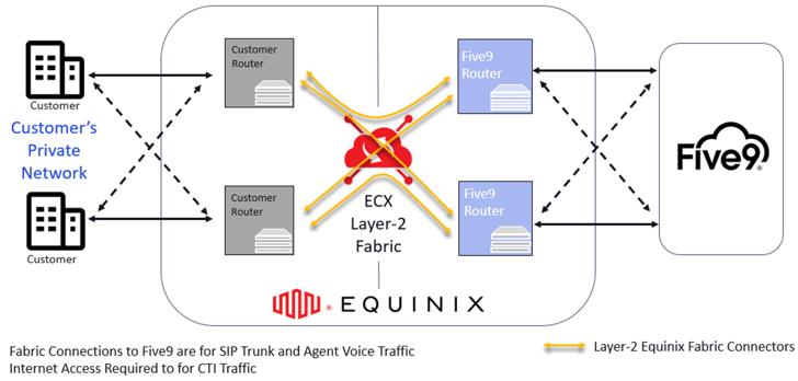
This topic explains the steps for connecting to Five9 Redundant Data Center Locations in Equinix Fabric. The process involves connecting to Five9 with dual redundant Fabric ports, and Fabric Layer2 Virtual Connections.
Five9 recommends customer Equinix Data Centers reside in the same region as Five9 Equinix Data Centers.
Dual Five9 Site Architectures
For customers connecting to two Five9 locations, the following architectures are recommended by Five9:
- Architecture 1 – Dual Sites, Dual Port: (recommended): Each customer site or location connects to two Five9 data center locations with two customer routers connected to dual Equinix Fabric ports. This ensures an availability SLA of 99.999%.
- Architecture 2 – Dual Sites, Single Port: Each customer site or location connects to two Five9 data center locations with a single customer router/switch connected to a single Equinix Fabric port. This ensures an availability SLA of 99.9%.
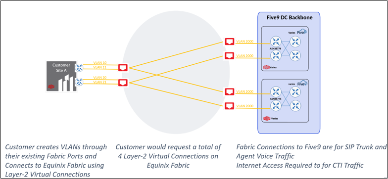
- Architecture 3 – Single Site, Dual Port: The customer site or location connects to two Five9 data center locations with two customer routers connected to dual Equinix Fabric ports.
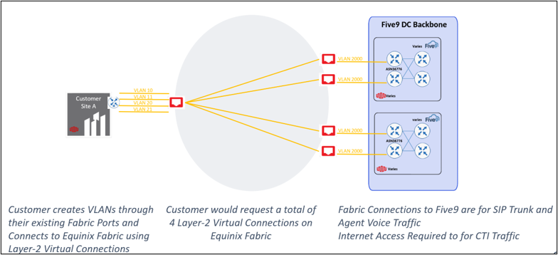
- Architecture 4 – Single Site, Single Port: The customer site or location connects to two Five9 data center locations with a single customer router connected to a single Equinix Fabric port.
Single Five9 Site Architectures
For customers connecting to a single Five9 site, the following architectures are supported:
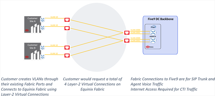
- Architecture 5 – Dual Sites, Dual Port, Single Five9 site: Each customer site or location connects to a single Five9 data center location with two customer routers connected to dual Equinix Fabric ports.
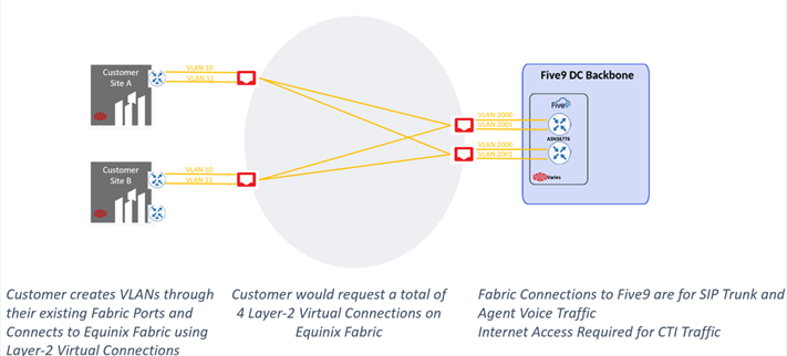
- Architecture 6 – Dual Sites, Single Port, Single Five9 Site: Each customer site or location connects to a single Five9 data center location with a single customer router connected to a single Equinix Fabric port.
- Architecture 7 – Single Sites, Dual Port, Single Five9 Site: The customer site or location connects to a single Five9 data center location with two customer routers connected to dual Equinix Fabric ports.
- Architecture 8 – Single Sites, Dual Port, Single Five9 Site: The customer site or location connects to a single Five9 data center location with two customer routers connected to dual Equinix Fabric ports.
Prerequisites
Before creating virtual connections to Five9 service using Fabric ports, you must have:
-
An Equinix Fabric account, with the following IAM roles assigned: Fabric Connections Manager.
-
At least two Fabric ports, each in separate metro locations.
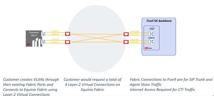
Architecture 1 – Dual Sites, Dual Ports
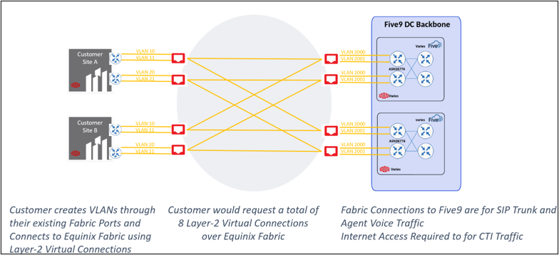
For this architecture, customers would create a total of 8 Virtual Connections between two different sites. The workflow for Architecture 1 is as follows:
First Customer Site
-
Log in to Equinix Fabric.
-
From the Connections menu, select Create Connection.
-
Click the A Service Provider card, and enter Five9 in the search field.
-
Click Create Connection.
-
Select the first Five9 destination location you’d like to connect to (e.g. Ashburn).
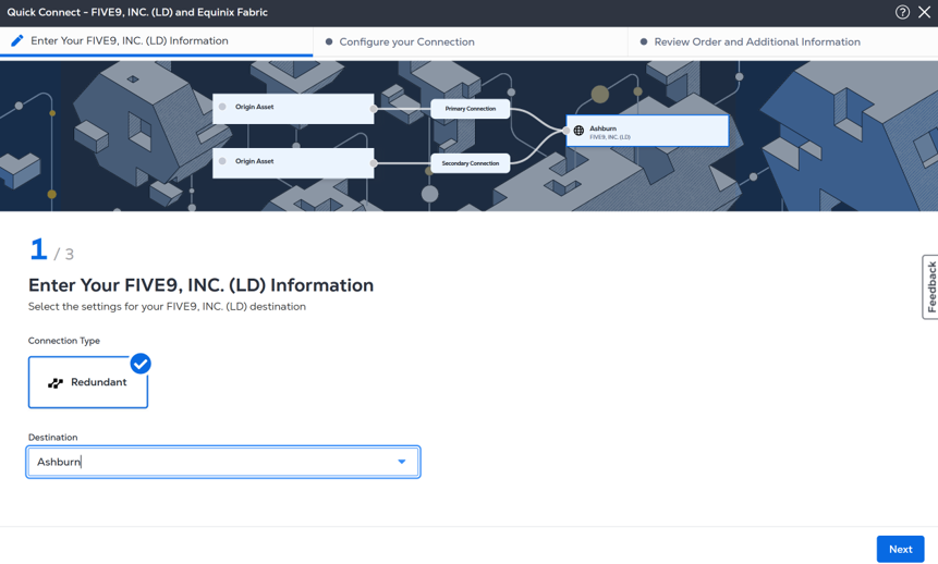
-
Click Next.
-
Select Port as the Origin Asset Type.
-
Under the Primary Connection section:
- Select the Primary Fabric Port at the first customer location (e.g. Asburn). Be sure the port is of Primary priority.
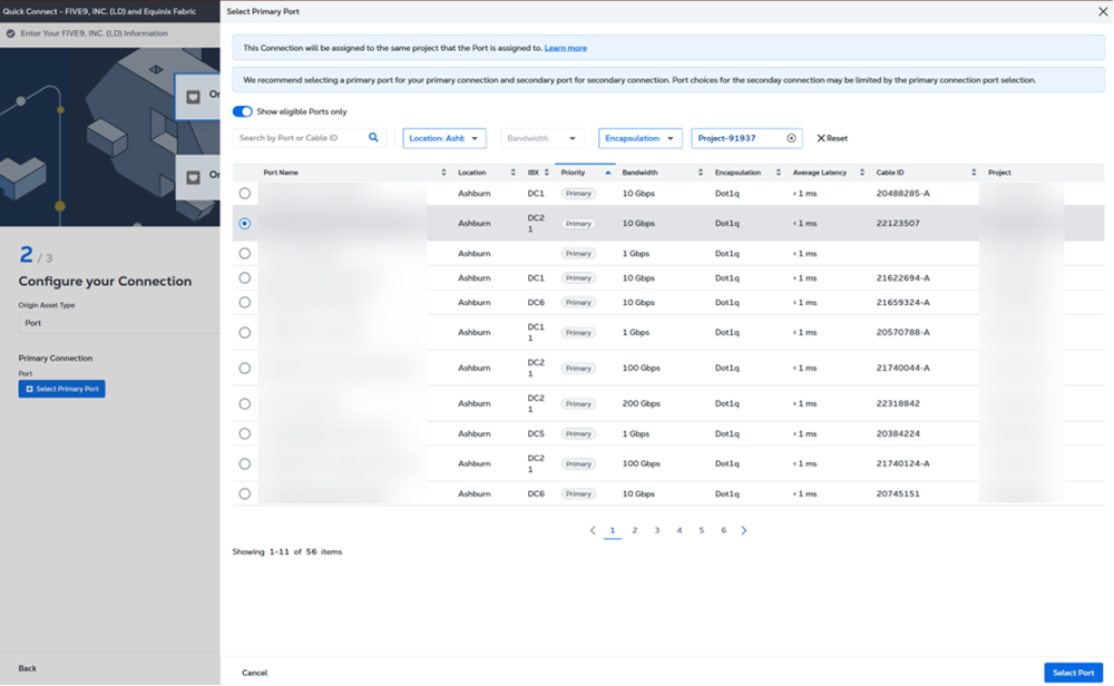
- Enter the primary Connection name.
- Select a bandwidth.
- Enter a VLAN ID (applicable to Dot1q ports) or a Customer VLAN Tag (C-tag) and a Service VLAN Tag (S-tag) (applicable to Qinq ports).
- Select the Primary Fabric Port at the first customer location (e.g. Asburn). Be sure the port is of Primary priority.
-
Under the Secondary Connection section:
- Select a Secondary Fabric Port at the first customer location (e.g. Asburn). Be sure the port is of Secondary Priority.
- Enter the secondary Connection name.
- Select a bandwidth.
- Enter a VLAN ID (applicable to Dot1q ports) or a Customer VLAN Tag (C-tag) and a Service VLAN Tag (S-tag) (applicable to Qinq ports).
-
Click Next.
-
Provide the email addresses of the recipients to be notified about the connection's status.
-
(Optional) Enter or add purchase order number.
-
(Optional) Provide customer reference identifier, that will help you identify this order on your invoice.
-
Review the connection details and click Create Connection.
Click Show Order Summary to see order details and connection pricing information.
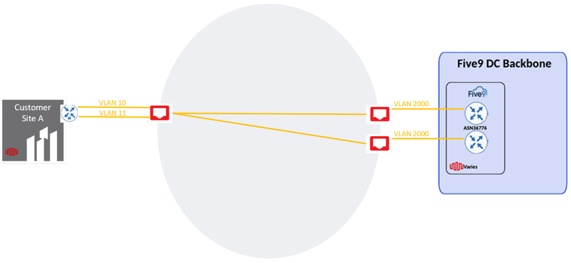
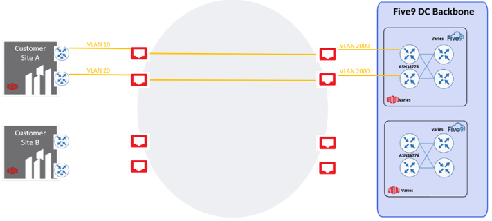
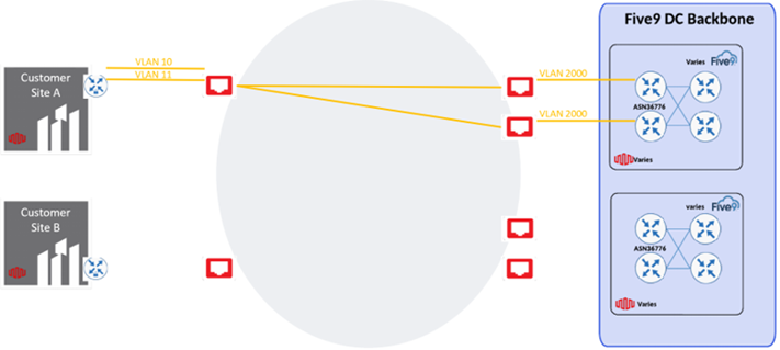
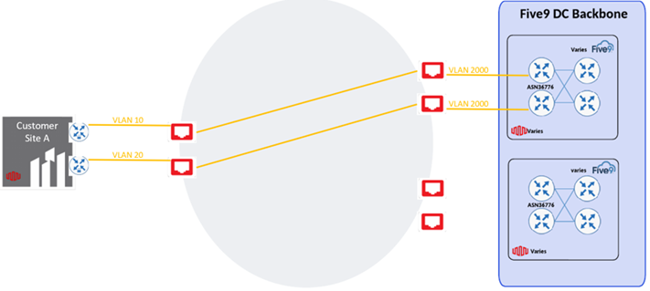
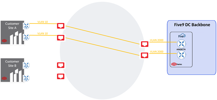
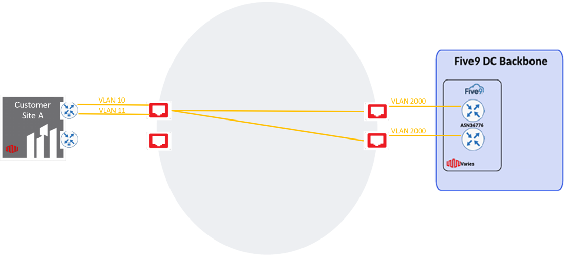
Once the connections are created, the topology will look as follows:
- Repeat steps 2 through 14. This time, select the second Five9 metro location (e.g. Chicago). Use the same Primary and Secondary Fabric ports at the first customer site.
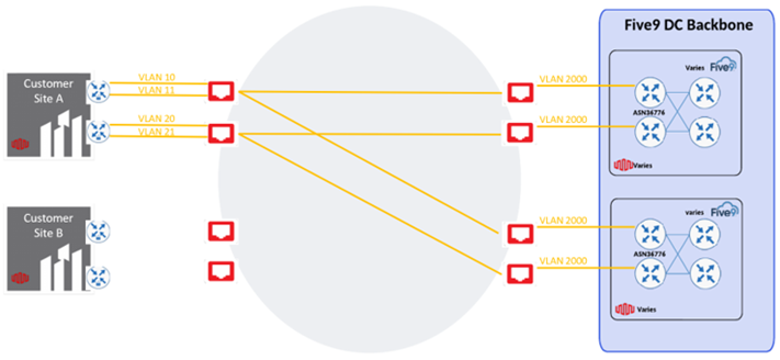
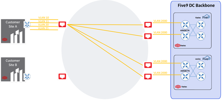
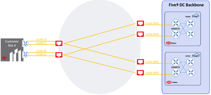
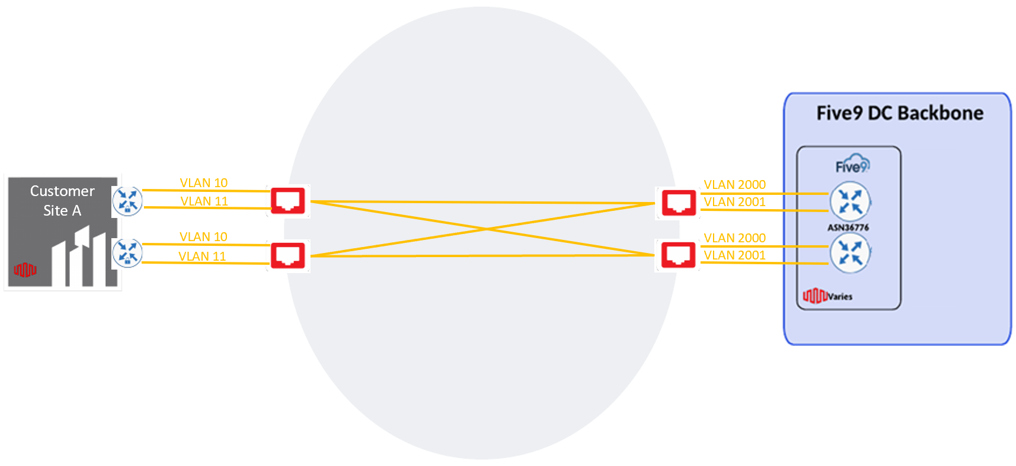
After repeating the steps for a second pair of redundant connections to Five9, the topology will be as follows:
Second Customer Site
For the second customer site, follow the same steps for the first customer, this time using the Fabric ports available at the second customer location.
-
Repeat steps 2 through 14 followed for the first customer site. Select the first Five9 metro location (e.g. Ashburn) and select the Primary and Secondary ports at the second customer location.
-
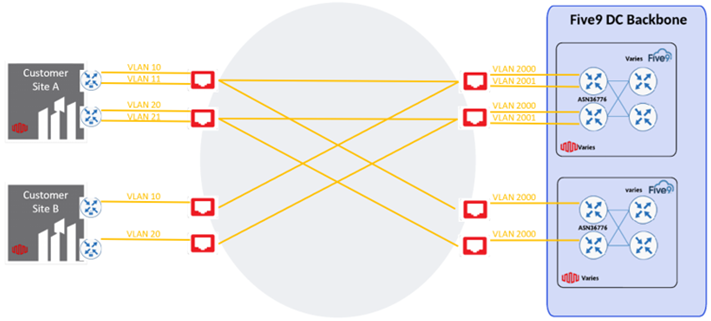
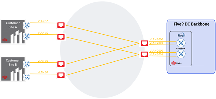
After repeating the steps for the first pair of redundant connections from the second customer location, the topology will be as follows:
-
Create the last pair of redundant connections to the desired location for Five 9 services by repeating steps 2 through 14.
-
Select the second Five9 metro location (e.g. Chicago) and select the Primary and Secondary Fabric ports at the second customer location.
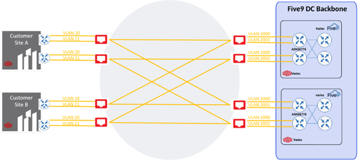
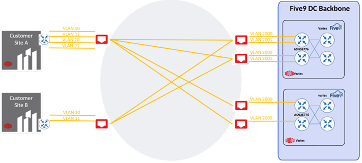
Once the last pair of redundant connections from the second customer site have been created towards Five9, the final architecture topology will appear as follows:
Architecture 2 – Dual Sites, Single Port
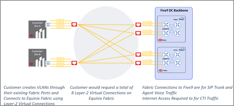
For this architecture, customers would create a total of 8 Virtual Connections between two different sites. The workflow for Architecture 2 is as follows:
First Customer Site
- Create the connections to the first customer site as instructed in the first 14 steps in Architecture 1.
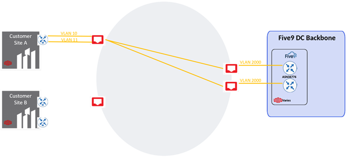
Once the connections are created, the topology will look as follows:
- Repeat steps 2 through 14. This time, select the second Five9 metro location (e.g. Chicago). Use the same Fabric Port and different VLAN IDs for each connection.
After repeating the steps for a second pair of redundant connections to Five9, the topology will be as follows:
Second Customer Site
Repeat the connection creation steps outlined for the first customer site but this time use the Fabric port available at the second customer site.
- Repeat steps 2 through 14. Select the first Five9 metro location (e.g. Ashburn). Use the same Fabric Port and different VLAN IDs for each connection.
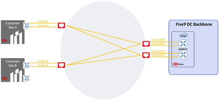
After repeating the steps for the first pair of redundant connections from the second customer location, the topology will be as follows:
- Create the last pair of redundant connections to the desired second location for Five9 services by repeating steps 2 through 14 This time, select the second Five9 metro location (e.g. Chicago). Use the same Fabric Port and different VLAN IDs for each connection.
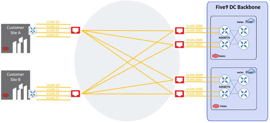
Once the last pair of redundant connections from the second customer site have been created towards Five9, the final architecture topology will be as follows:
Architecture 3 – Single Site, Dual Ports
For this architecture, customers would create a total of 4 Virtual Connections from a single site. The workflow for Architecture 3 is as follows:
Single Customer Site
- Create the connections to the customer site as instructed in the first 14 steps in Architecture 1.
Once the connections are created, the topology will look as follows:
- Repeat steps 2 through 14. This time, select the second Five9 metro location (e.g. Chicago). Use the same Primary and Secondary Fabric ports at the single customer location.
After repeating the steps for a second pair of redundant connections to Five9, the topology will be as follows:
Architecture 4 – Single Site, Single Port
For this architecture, customers would create a total of 4 Virtual Connections from a single site. The workflow for Architecture 4 is as follows:
Single Customer Site
- Create the connections to the customer site as instructed in the first 14 steps in Architecture 1.
Once the connections are created, the topology will look as follows:
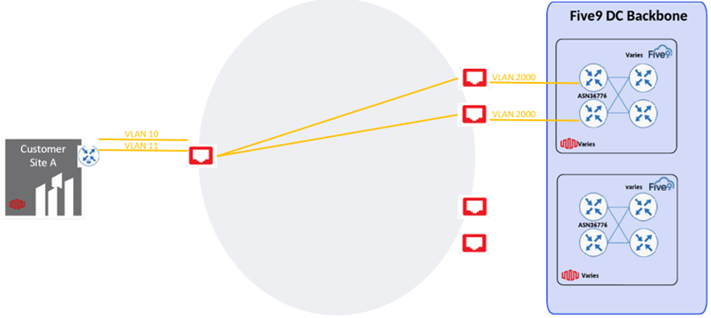
- Repeat steps 2 through 14. This time, select the second Five9 metro location (e.g. Chicago). Use the same Fabric Port and different VLAN IDs for each connection.
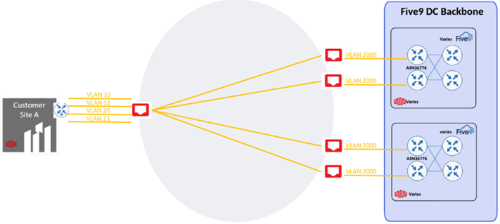
After repeating the steps for a second pair of redundant connections to Five9, the topology will be as follows:
Architecture 5 – Dual Sites, Dual Ports, Single Five9 Site
First Customer Site
For this architecture, customers would create a total of 4 Virtual Connections between two different sites. The workflow for Architecture 5 is as follows:
Create the connections to the customer site as instructed in the first 14 steps in Architecture 1.
Once the connections are created, the topology will look as follows:
Second Customer Site
For the second customer site, customers should follow similar steps as outlined for the first customer site but now using the Fabric ports available at the second customer location.
Repeat steps 2 through 14. Select the single Five9 metro location (e.g. Ashburn) and select the Primary and Secondary ports at the second customer location.
After repeating the steps for the redundant connections from the second customer location, the final topology will be as follows:
Architecture 6 – Dual Sites, Single Port, Single Five9 Site
First Customer Site
For this architecture, customers would create a total of 4 Virtual Connections between two different sites. The workflow for Architecture 6 is as follows:
Create the connections to the customer site as instructed in the first 14 steps in Architecture 1.
Once the connections are created, the topology will look as follows:
Second Customer Site
Repeat the connection creation steps outlined for the first customer site but now using the Fabric port available at the second customer site.
Repeat steps 2 through 14. Select the single Five9 metro location (e.g. Ashburn). Use the same Fabric Port and different VLAN IDs for each connection.
After repeating the steps for the redundant connections from the second customer location, the final topology will be as follows:
Architecture 7 – Single Site, Dual Ports, Single Five9 Site
Single Customer Site
For this architecture, customers would create a total of 4 Virtual Connections from a single site. The workflow for Architecture 7 is as follows:
Create the connections to the customer site as instructed in the first 14 steps in Architecture 1.
Once the connections are created, the topology will look as follows:
Repeat steps 2 through 14. This time, use the Secondary port at the single customer site to connect to Five9’s single site.
After repeating the steps for a second pair of redundant connections to Five9, the topology will be as follows:
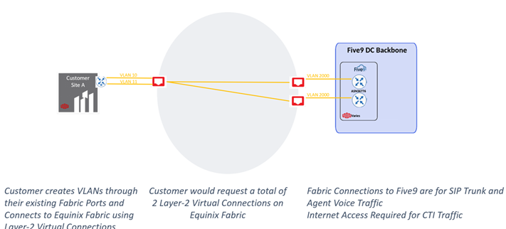
Architecture 8 – Single Site, Single Port, Single Five9 Site
For this architecture, customers would create a total of 2 Virtual Connections from a single site. The workflow for Architecture 8 is as follows:
Create the connections to the customer site as instructed in the first 14 steps in Architecture 1.
Once the connections are created, the final topology will look as follows: