Sub-Interface Connections to a Colocation Physical Port
Sub-interfaces are a construct used on network devices to divide a single physical or virtual interface into multiple logical Layer 3 network interfaces. When a routed interface on a network device is connected to a port where multiple 802.1Q tagged traffic is transmitted, this routed interface can be configured as trunk port, by dividing a single interface into multiple logical layer 3 network interfaces.
Network Edge now supports sub-interface on its virtual device across metros connected to the physical equipment ports located in the customer’s own co-location.
Support of the sub-interface features for Network Edge:
- Sub-interface function needs to be supported by vendor VNF
- 802.1Q Port (Colocation side) is supported. Q-in-Q port is not supported currently.
- Bring Your Own Connection (BYOC) is not currently supported for sub-interfaces.
Configuration
To configure a connection that allows 802.1Q connections to the selected virtual device:
-
Sign in to the Equinix Customer Portal and navigate to Network Edge.
-
Click Create Connection.
-
On the My Own Assets card, click Connect to My Own Assets.

-
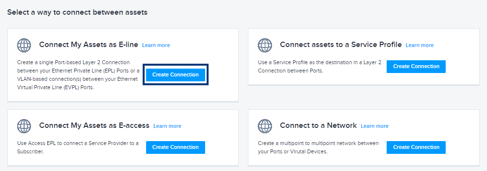
On the Connect My Assets as E-line card, click Create Connection.
-
On the Select Locations page, in the Origin (A-side) section, select Virtual Device and the following options:
- Location – Select the Metro in which your device is located.
- Virtual Device Type - Select the device type you are connecting: Virtual Devices, Redundant Devices, or Clusters.
- Connection Type - Select the type of connection you are making: Single Connection or a Redundant Connection. Note that these options are filtered on what Virtual Device Type you selected.
- Finally, select the Virtual Device that you are connecting to your colocation.
-
In the Destination(Z-side) section, select:
- Your colocation's Metro location.
- The Dot1Q port to which you are connecting your device.
-
Click Next.
-
On the Connection Detail page:
- Enter a name for your connection in the Connection field.
- In the Connection Type section, select Tagged.
- Select VLAN Range radio button to configure VLAN range included in this 802.1Q connection. For instance, if the port allows VLAN ID 5, 10, 15, 20 (4 VLANs), then you need to define the range as 5-20.
infoYou can’t specify multiple VLAN IDs individually.
-
Select Tagged and enter the VLAN Range for the secondary device if you are creating a redundant connection.
-
Select the Connection Speed.
-
Select the interface.
Validate Configuration and VLAN Range Setting
- On the Connections menu, select Connections Inventory.
- Click the VLAN Tagging attribute in the Origin and Destination columns to display the VLAN range information.
- Click the cog icon and select VLAN Tagging.