Platform Architecture
This topic focuses on the guiding principles and standards of the architecture. The software stack and major components of the OSS/BSS, as well as the “packet walk” from virtual devices to the cloud and other destinations are covered.
The Network Edge architecture includes a fully capable stack of hardware, software, and design principles that derive from multiple standards bodies and vendors.
General Trends and Standards
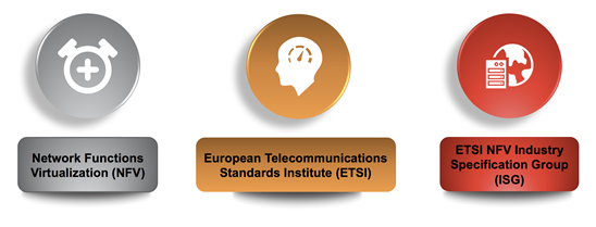
Equinix has built a full stack platform for the Network Edge based on the standards set forth by ETSI, the European Telecommunications Standards Institute. Specifically, the ETSI established an NFV Industry Specification Group that has defined much of the landscape for network functions virtualization.
The ETSI NFV framework consists of three major components:
- Network Functions Virtualization Infrastructure (NFVI): A subsystem that consists of all the hardware (servers, storage, and networking) and software components on which Virtual Network Functions (VNFs) are deployed. This includes the compute, storage, and networking resources, and the associated virtualization layer (hypervisor).
- Management and Orchestration (MANO): A subsystem that includes the Network Functions Virtualization Orchestrator (NFVO), the virtualized infrastructure manager (VIM), and the Virtual Network Functions Manager (VNFM).
- Virtual Network Functions (VNFs): The software implementation of network functions that are instantiated as one or more virtual machines (VMs) on the NFVI.
Overlaid on this framework is legacy, current, and new operational and business support systems that Equinix has procured or built over the years, resulting in a standardized architecture:
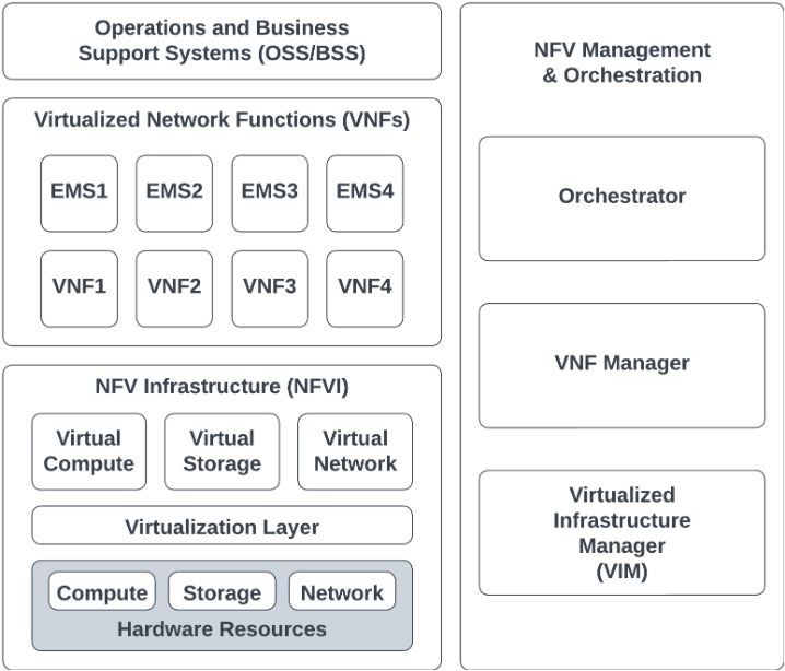
Within each component are multiple systems, some of which are described in more detail below.
The core concept behind NFV is to implement these network functions as pure software that runs over the NFVI. A VNF is a virtualized version of a traditional network function, such as a router or firewall – but it could also be a discrete action such as NAT or BGP. This concept is radically different from the traditional hardware deployment implementation in many ways. Decoupling of the software from the hardware allows the lifecycle and development of each of these network functions in separate cycles. This decoupling allows for a model where the hardware/infrastructure resources can be shared across many software network functions.
A VNF implementation (like a virtual router or virtual switch) doesn’t usually change the essential functional behavior and the external operational interfaces of a traditional Physical Network Function (PNF), like a traditional router or a switch.
The VNF can be implemented as a single virtual machine, multiple VMs, or a function implemented within a single shared VM with other functions.
Network Architecture and Equipment
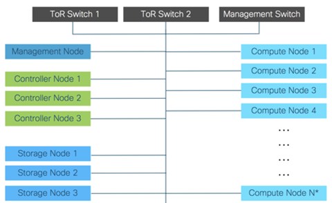
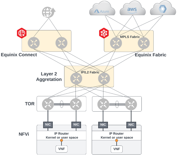
Within the NFVi component of the architecture resides most of the hardware deployment. Equinix deploys a full complement of compute nodes, management devices, top of rack aggregation switches, border routers to other services, storage, and other aspects that enable the full suite. The depth and size of each deployment can vary depending on market, projections, capacity and other factors.
We refer to this full suite as a Point of Deployment, or POD. Each POD is independent of every other POD, even if more than one POD is deployed in the same metro.
A full POD also includes redundant top of rack aggregation switches and management switches for internal use such as operations/support, monitoring or ongoing orchestration of new assets.
Within the POD Equinix hosts virtual machines that run the software images of each VNF. Our VMs are KVM-based and the infrastructure is on an Openstack platform.
Each virtual device is logically connected to the aggregation switches and interconnection platforms above it using VXLAN technology, and a VPP orchestrates the networking between them and in and out of the POD:
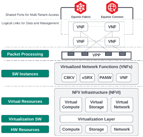
The VPP is the vector packet processing software that makes intelligent decisions about switching and routing of packets. The VPP passes traffic back and forth to Equinix Fabric and EC (Internet) interconnection platforms and maintains full redundancy in case of failures at the POD level. For information about redundant and resilient architecture, see Architecting Resiliency.
System/Stack Architecture
The NFV Management and Orchestration suite has several key software components that facilitate the platform. This portion of the reference architecture is often referred to as management and orchestration (MANO)
- Virtual Infrastructure Management (VIM) – Handles the instantiation, configuration, reservation, and other functions of the compute, storage, and other traditional infrastructure elements.
- Virtual Network Functions manager (VNFM) – Handles lifecycle, monitoring, and other activities of active virtual devices. Runs the workflow of deploying a device, change management, and ultimately teardown/deletion of devices.
- Network Functions Virtualization Orchestrator (NFVO) – ensures that the right configs are loaded to software images, inventory is fetched and reserved (such as IP addresses and VXLANs), and other features where coordination with other systems and OSS/BSS are required.
Equinix maintains redundant orchestrators in each region. When a request is made through the portal or API, it reaches into the relevant orchestrator to begin the process of reserving assets, inventory, and selecting an appropriate configuration and image for the requested device or service.
Here is an example of the flow and interaction between the various systems in a specific region:
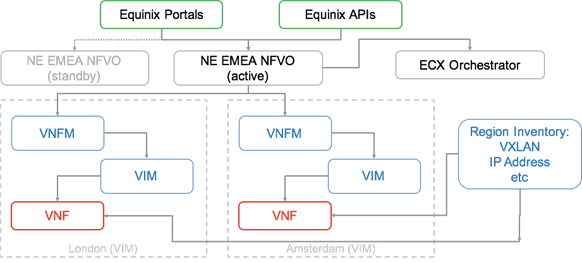
When needed, the Network Edge orchestrator interacts with the Equinix Fabric orchestrator to coordinate activities of activating a connection from the interface of a VNF to the cloud or other destination of choice. Each activity is regularly checking inventory to see what is available and reserve bandwidth, IP addressing, VLANs or other logical resources so that they are not taken by any other device in the platform.
Equinix also includes a host of internal management and monitoring tools, some parts which you might see.
Our suite includes:
-
Monitoring
- Health and performance of physical and logical assets, such as CPU and RAM utilization
- POD-level views into physical and virtual active components and objects
-
Analysis and Reporting
- Service impact analysis to determine the relationships between different components and the effect each has on the other when changes or events occur
- POD capacity forecasting – let's our engineers know in advance when augments to compute, network, or other assets is going to be needed
-
Automation
- Auto-discovery when capacity is augmented and added to the POD or uplinks to other platforms, and quickly becomes usable
- Reports on and reacts to POD-level health and changes
- Fully integrated with the VIM
Stitch It Together: Packet and Traffic Flow
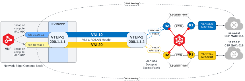
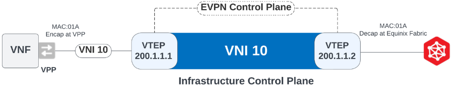
Network Edge uses EVPN/VXLAN for the control and data plane functions. The main purpose for the Layer 2 control plane and MAC learning is to establish Layer 2 reachability between the VNF and the respective CSP router. Once Layer 2 connectivity is established, Layer 3 peering can be established between the VNF and its respective peer. Therefore, only two MAC addresses are learned across a single VNI because that is all that is needed for connectivity, while many MAC addresses are learned across the VTEP (two for each VNI). The following shows the data flow from the middle working outward to establish route peering.
The infrastructure control plane consists of EVPN between the compute VTEP and Equinix Fabric VTEP to enable dynamic MAC address learning while VXLAN is used as the data plane between the compute and Equinix Fabric nodes. Additionally, the VNI is mapped to the VPP vSwitch and the MAC address gets encapsulated on ingress to the VPP and tagged in the example below with the VNI of 10.
Before an overlay control plane session between the private cloud and VNF can be established, one more leg of the Layer 2 control plane between the Equinix Fabric and the respective private cloud must exist. During the provisioning process when connecting to a CSP a VLAN gets dynamically instantiated and connected to the Equinix Fabric switch, typically over a .1q connection. The MAC address of the CSP is then learned over this .1q trunk port as shown below. In the example below, MAC:01B from the CSP is learned at the physical port on the Equinix Fabric switch through VLAN 462. The last connection needed to complete the Layer 2 control plane is done through routing instances (RI) on the Equinix Fabric switch which forms an internal link for the EVPN session. Once the last leg of the Layer 2 control plane has been completed, the overlay Layer 3 control plane for BGP peering can be established.

The entire solution looks like this end to end: