Device Link Groups
A Device Link Group (DLG) is a Network Edge service with which two or more virtual devices can be connected as a group within or across multiple metros. A DLG is typically used for service chaining (connecting multiple device types such as firewall and routers, together), backbone, or for redundancy purposes.
The device link service creates a Layer 2, full-mesh LAN between two or more Network Edge devices that a user can access.
Device linking can be used to accomplish several use cases:
- Connect virtual devices together across Metros to create a WAN or other private network configuration.
- Direct traffic flow from one device to the next in sequence, or “service chain” items together.
- Connect redundant devices together to synchronize them using relevant protocols.
Device links only establish the layer 2 connectivity and do not specify the exact routing or traffic flow at Layer 3. This must be created through configuration of the interface protocols and other needs.
Although the device link is a Layer 2 construct, the IP addressing, Global ASN, and some other steps are necessary for a proper configuration.
The device link service has the following attributes and specifications:
| Data Requirements | Notes | |
|---|---|---|
| Device | Virtual device name | Specify each device that is part of the overall link group. The number of devices allowed in a single DLG is limited to 29 devices. However there are practical limitations to routing, so we recommend that no single group exceed 10-12 total devices. |
| Device Link Group Name | Can’t exceed 50 characters; must be unique to your account. | Common group name that requires the use of a single interface on each device that is part of the group. |
| Device Interface | Each device in the group requires a single interface that’s dedicated to the device link group; the system automatically determines next available interface to assign. | A device can be part of more than one group, but each device is on a discrete interface. |
| IP Address Pool | This option must be IPv4 and in CIDR format: single subnet only. IP Address pool is a required field when creating a DLG. | The IP address can be a public or private address and it is user-defined. When devices are added to the pool, each is assigned an overlay address from the subnet until the subnet is exhausted. Once exhausted, the device link can’t accept additional devices. While most users usually have small groups, the IP address pool can't be augmented or added to once it’s defined. We recommend that you place a large enough pool on the group so there is little risk of exhaustion in the future. |
| IP Address Interface | The IP address needs to be configured manually using device CLI. | As devices are added, an IP address is allocated to the interface from the defined pool or subnet. |
| Metro throughput/ Speed | Whole number from 1-10000 | Measured in Mbps; this is the total possible throughput in and out of the metro |
| Global ASN | Each device in the group must have an ASN specified to conduct BGP peering. The global ASN needs to be configured manually using device CLI. | This Global ASN setting is not exclusive to Device Link, but if no other services or settings have been created when a device is added to the group, an ASN must be specified for the device. If a Global ASN was already specified for a connection, VPN tunnel, or other service, the system automatically uses that ASN instead. |
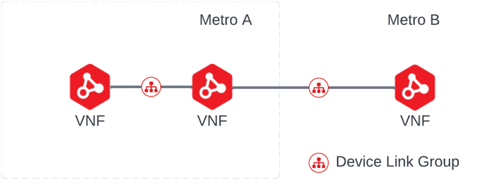
To create a device link among multiple devices, a unique Device Link Group needs to be defined. This group has a common name and requires the use of a single interface on each device that’s part of the group. A device can be part of more than one group, but each device is on a discrete interface:
Users can add one device per metro per device link group. Traffic travels from one device to another between the Metros using the same backbone Equinix Fabric uses.
Device Links can be created using Network Edge APIs. For more information, see Network Edge API – Create Device Link.
DLG Throughput Considerations
The traffic that moves in and out of a metro is policed as a single measure of throughput for each metro. This is important to understand so that users can set up the device link to optimize the traffic flow and overlay routing that is intended.
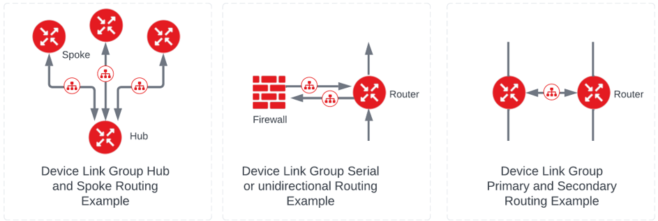
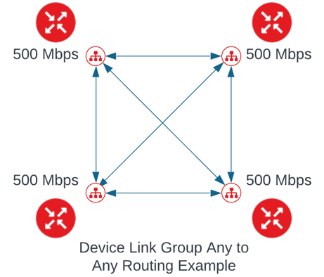
For example, in a full mesh setup users typically have the same throughput setting in every metro, as shown:
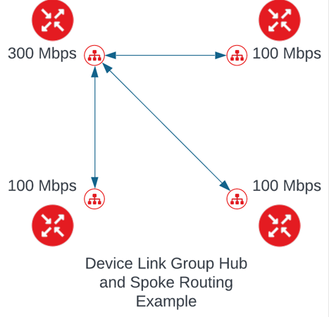
Alternatively, if the intention with a Device Link group is to set up a hub and spoke routing schema, users can add throughput limits like the below:
As functionality is added to allow more than one device per metro into a device link, this design and throughput setup becomes critical. This configuration remains a per metro setting, not a per device throughput setting. Within the metro, there is no enforced throughput policy, but there might be other limitations, such as the throughput of the device itself, the available capacity in the compute node or the best effort traffic competing with other traffic.
When more traffic flows to or from a metro than is allocated (such as from routing design or throughput), packets are dropped as it's a best effort service. Users can edit and change the amount allowed for each metro at any time.
Because a single device can be part of multiple device links, users can also use this to overlay unidirectional traffic patterns for some use cases, such as firewalls that filter traffic and then return it to another device. The diagram below is an example of this:
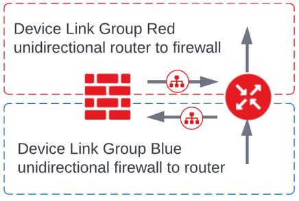
Device link is always capable of being bidirectional, depending on the overlay routing rules that the user creates.
Device Link and Device Redundancy
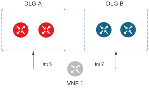
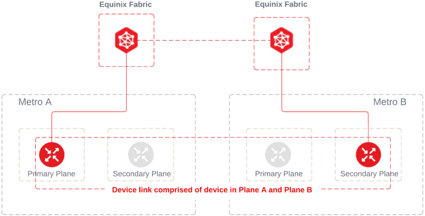
A device link can contain any combination of primary and secondary devices that are also part of a redundant pairing. This is the case even if the combination does not represent the same pairs. For example, a device link could theoretically include the primary device of redundant pair A and the secondary device of redundant pair B.
Some Virtual Devices can be restricted from using device links due to settings that are native to the vendor or the current configuration. The system indicates when a device is not eligible to be part of a device link. Here are some examples of why a Virtual Device can’t be allowed:
- The device has no more interfaces available
- The device is already part of the same group (it can't be added twice).
- There are no additional IP addresses to allocate from the original customer pool that was defined.
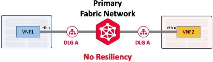
Device Link Redundancy
Device Link Groups (DLGs) can be created with or without redundancies. It is important to understand how redundant DLGs are created for better resilient architecture of the Network Edge service. See Device Link Resiliency for more information.