Architecting for Resiliency
This topic provides an overview of the fault-tolerant solutions that you can achieve using Network Edge.
Designing solutions with resiliency is one of the most critical aspects of network and edge architecture. While there is no correct answer to how much resiliency is needed, there are best practices, suggestions for different use cases, and some specific services and features that Network Edge offers.
The underlying Network Functions Virtualization (NFV) platform that provides the infrastructure for Network Edge is inherently fault-tolerant from a single virtual instance standpoint. Still, you must design resiliency into the overall solution to achieve the maximum redundancy possible. This document explains how to achieve resiliency using the inherent nature of the platform complemented by Network Edge fault-tolerant features.
Levels of Redundancy
Imagine a network design from the origin of a data packet and moving from inside outward to its destination. In that case, each point where traffic is processed or traversed becomes a possible point of failure. The key is to design against an impacting event at the traversal points.
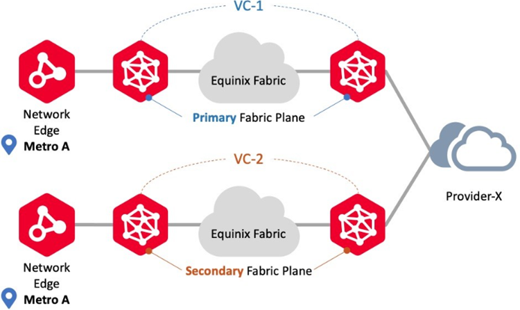
In a simple network flow from a Network Edge device to an Equinix Fabric participant, as shown in the next graphic, the traffic flows have three distinct points: Network Edge virtual device, Equinix Fabric, and the Fabric participant connection. There is inherent redundancy between the Network Edge virtual device and Equinix Fabric, so the Leaf or Spine architecture that interconnects the underlying NFV platform to the Fabric is redundant. There is no inherent redundancy between Equinix Fabric and the Fabric participant. To achieve maximum redundancy, you must deploy a solution that utilizes different planes of connectivity to take advantage of the complete network flow.

Primary and Secondary Planes
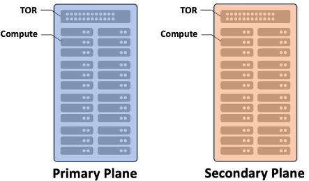
The Network Edge is built upon a standard data center redundancy architecture with multiple point of deployments (PODs) that have dedicated power supplied. The concept of Primary and Secondary planes is behind the deployment of Network Edge and Equinix Fabric. Network Edge utilizes the Primary and Secondary planes using compute separation through affinity. Each virtual device in a fault-tolerant pair is deployed in its respective cluster. While referred to as Primary Plane and Secondary Plane, there are multiple compute planes in each Network Edge PODs. The actual number varies based on the size of the metro. This allows devices to be deployed in a manner where they are not co-mingled on the same compute plane, eliminating compute as a single point of failure (SPOF).
Equinix Fabric switches are part of a chassis group that consists of Primary and Secondary switches. The Primary and Secondary switch designations for the chassis group are simply a way to identify the switches from a nomenclature standpoint and do not show traffic flows. Active-Active or Active-Standby from a routing standpoint are configured on Network Edge device and are completely under your control. The Platform Architecture documentation discusses more details on the Network Edge foundational architecture.
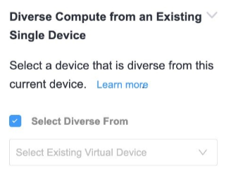
A firewall VNF called NGFW-A is deployed previously. To deploy a router VNF on the secondary plane, use Diverse Compute from an Existing Single Device feature and select NGFW-A from the drop-down menu.
Device and Connection Resiliency Defined
Network Edge offers multiple resiliency options that can be summarized as device options and connection options. Device options are local and provide resiliency against failure at the compute and device level in the local metro. This is analogous to what the industry typically refers to as “High Availability (HA)”. Connection resiliency is a separate option for customers that require additional resiliency with device connections (DLGs, VCs and EVP-LAN networks).
It is common to combine both local resiliency and connection resiliency, but it is not required - Ultimately it depends on the customer’s business requirement.
Geo-redundancy is an architecture that expands on local resiliency by utilizing multiple metros to eliminate issues that may affect Network Edge at the metro level. Geo-redundancy is discussed in detail here.
Single (Standalone) Devices – Local Resiliency Option
Single or standalone devices have no resiliency for compute and device failures. The first single device is always connected to the Primary Compute Plane. Single devices always make connections over the Primary Fabric network. Single devices can build redundant connections (VCs, DLGs, etc.) but they will always traverse the Primary Fabric plane. Single devices can be converted to Redundant Devices via the anti-affinity feature.
Single Device Anti-Affinity
As described earlier, single devices have no resiliency by default. However, single devices can be placed in divergent compute planes. This is commonly called anti-affinity and is available in the device creation workflow. Under the Diverse Compute from an Existing Single Device section, checking the “Select Diverse From” box allows customers to add new devices that are resilient to each other.
Redundant vs. Cluster Virtual Device
Network Edge workflows ensure paired virtual devices in a fault-tolerant deployment are placed on Primary and Secondary compute planes. There are two types of fault-tolerant deployments: Redundant devices and Clustered devices.
These options provide local (intra-metro) resiliency to protect against hardware or power failures in the local Network Edge POD. By default, the two virtual devices are deployed in separate compute planes (Primary and Secondary) and they are distinct from each other. The primary device is connected to the Primary Fabric network and the secondary/passive device is connected to the Secondary Fabric network. The deployment type selection is available from the device creation workflow in the portal.
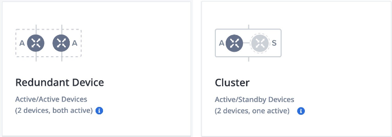
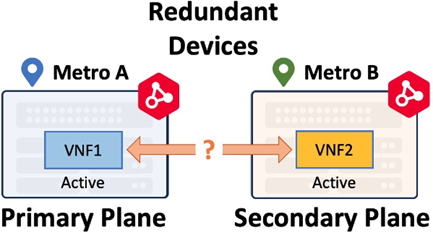
Redundant virtual instances are deployed on different compute planes for redundancy. They have no higher-level workflows, meaning the devices are unaware of each other after initial deployment and function as two distinct virtual devices. Typically, redundant devices function in an Active-Active fashion. Redundant virtual instances can be deployed in a same metro or across metros. Redundant device in a single metro only provides local resiliency. Geo-redundancy deployment (redundant devices across metros) provides much higher resiliency. When a redundant device is deployed in another metro, it is still deployed in the secondary compute plane.
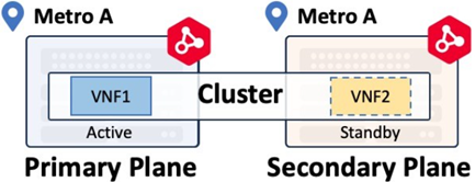
Cluster virtual instances have higher-level workflows that will deploy an Active-Standby device pair as defined by the respective vendor. Check the documentation to verify Cluster support for your virtual device. Cluster devices can only be deployed within the same metro.
Virtual Connections
Virtual connections allow you to specify the level of resiliency your deployment requires. The workflows are flexible, allowing for multiple scenarios to accommodate redundancy, if required.
Virtual connection workflows differ between Redundant and Cluster deployments. Redundant device connections originate from each individual virtual device in the redundant pair, while clustered device connections originate from the cluster.
Redundant Virtual Connections
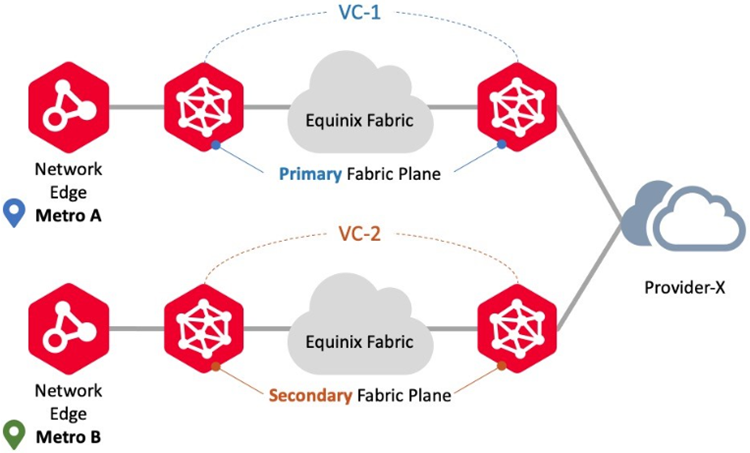
Redundant devices are deployed on different compute planes using affinity. Once deployed, the devices do not share any configuration information and function as two independent devices. To achieve redundancy through to the Fabric participant, you create virtual connections on the Primary and Secondary Fabric as shown below. Primary plane connects to the Primary Fabric network (or Primary Fabric Plane) and Secondary plane connects to the Secondary Fabric network.
This is one of the most important concepts for understanding Network Edge resiliency. The device plane determines which Fabric network (or Fabric Plane) is used for device connections.
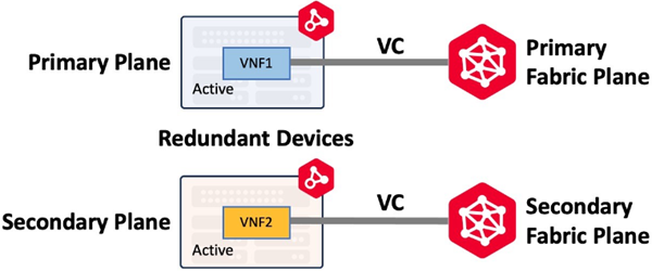
Redundant devices can be deployed in the same metro or in different metros allowing you to build redundant solutions that span geographic distances. Workflows are flexible and you can create connections on both the primary and secondary Fabric plane or on each plane as needed for your use-case.
Cluster Virtual Connections
Clustered devices are deployed on primary and secondary compute planes and have higher-level workflows to build either an Active-Active or Active-Standby pair of virtual devices.
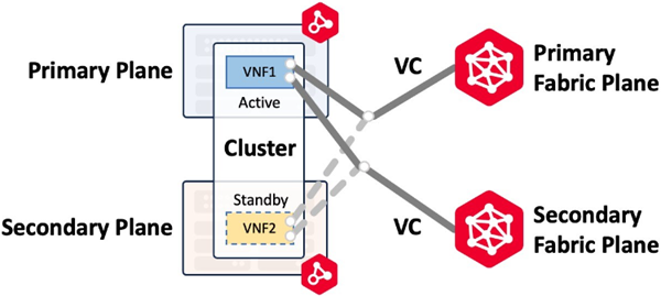
Clusters can be built in the same metro only. For example, if a virtual circuit is built on both the primary and secondary Fabric plane, the workflow will create two connections to the cluster and assign an interface for each connection to both Cluster nodes. The image below (Connecting to Same Metro/Same Provider) shows a primary and secondary Fabric connection to an Active-Standby cluster with cluster-node0 active and cluster-node1 standby. In the event of a cluster failover and cluster-node1 becomes active the connections are moved to cluster-node1.
| Redundant Devices | Clustered Devices | |
|---|---|---|
| Deployment | Two devices, both Active, appearing as two devices in the Network Edge portal. Both devices have all interfaces forwarding | Two devices, only one is ever Active. The Passive (non-Active) device data plane is not forwarding |
| WAN Management | Both devices get a unique L3 address that is active for WAN management | Each node gets a unique L3 address for WAN management as well as a Cluster address that connects to the active node (either 0 or 1) |
| Device Linking Groups | None are created at device inception | Two are created by default to share configuration synchronization and failover communication |
| Fabric Virtual Connections | Connections can be built to one or both devices | Single connections are built to a special VNI that connects to the Active Cluster node only. Customer can create optional, additional secondary connection(s) |
| Supports Geo Redundancy | Yes, Redundant devices can be deployed in different metros | No, Cluster devices can only be deployed in the same metro |
| Vendor Support | All vendors | Fortinet FortiGate FirewallsJuniper vSRX FirewallsNGINX PlusPalo Alto VM-Series Firewalls |
All scenarios shown in the following illustrations assume the Provider participant connects to both the Primary and Secondary Fabric. If there are any questions about redundant Fabric connections, consult with your Equinix Global Solution Architect.
Connecting to Same Metro/Same Provider
Use this connection scenario to connect to the same provider using Network Edge devices in the same metro location. In this scenario, Network Edge supports both Redundant and Cluster deployments. Virtual circuit workflows ensure each circuit is provisioned on the Primary and Secondary Fabric planes, respectively. An example is redundant connections to the same Fabric participants.
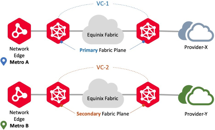
Connecting to Same Metro/Different Providers

Use this connection scenario to connect to different providers using Network Edge devices in the same metro location. In this scenario, Network Edge supports both Redundant and Cluster deployments. Virtual circuit workflows ensure each circuit is provisioned on the Primary and Secondary Fabric planes, respectively. An example is redundant connections to different Fabric participants.
Connecting to Different Metro/Same Provider
Use this connection scenario to connect to the same providers using Network Edge virtual instances in different metro locations. In this scenario, Network Edge supports Redundant deployments but does not support Cluster deployments. Virtual circuit workflows ensure each circuit is provisioned on the Primary and Secondary Fabric planes, respectively. An example is redundant connections from two different metros to the same Fabric participant.
Connecting to Different Metro/Different Providers
Use this connection scenario to connect to different providers using Network Edge devices in different metro locations to different Fabric participants. In this scenario, Network Edge supports Redundant deployments but does not support Cluster deployments. Virtual circuit workflows ensure provisioning for each circuit on the Primary and Secondary Fabric planes, respectively. An example is redundant connections from two different metros to the different Fabric participants.
Device Link Groups
A Device Link Group (DLG) is a Network Edge service with which two or more virtual devices can be connected as a group within or across multiple metros. A DLG is typically used for service chaining (connecting multiple device types such as firewall and routers, together), backbone, or for redundancy purposes.
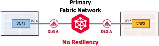
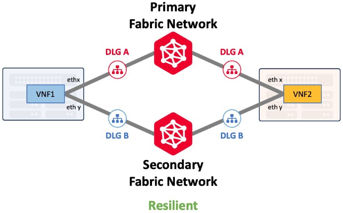
DLGs can be created with or without redundancy. A single DLG, like a single Ethernet cable, provides no resiliency. Customers that require maximum resiliency should deploy additional DLGs that connect to both the Primary and Secondary Fabric networks.
Device Link and its redundancy capability is discussed in detail in Device Link Resiliency.
EVP-LAN Networks
Network Edge supports EVP-LAN connection to allow multipoint-to-multipoint networking. EVP-LAN enables you to interconnect your data center assets across many locations through a common network instead of requiring direct connections between individual locations. This topic describes how to create a private multipoint-to-multipoint network and connect to that network from your Network Edge devices.
EVP-LANs differ from the DLGs in that they connect to Network Edge devices and Fabric ports. Multiple Network Edge devices in the same metro can be part of the same EVP-LAN network. Customers that require maximum resiliency should deploy additional EVP-LANs that span both the Primary and Secondary Fabric networks.
For proper resiliency, each device in the Redundant device pair will require a single connection to two different EVP-LAN networks. The Primary device on the Primary plane will use the Primary Fabric network. The Secondary device on the Secondary plane will use the Secondary Fabric network.
Clustered devices are different in that the workflow allows connections to be built to either the Primary or Secondary Fabric networks.
Related Topics